To install the ProntoPLACE software click or cut and paste into your browser the following link:
https://www.unisoft-cim.com/download/requests/place/place.zipAfter the download is complete unzip PLACE.ZIP then double-click on PLACE.EXE and follow the instructions on the screen to install the software. Please accept the default path on installation, it can be changed later.
The software is now installed and ready to use.
Installation troubleshooting: Go to https://www.unisoft-cim.com/installation-troubleshooting.html
We are available anytime to go online with you and help you review the Unisoft software. Also the software has HELP for most menu items by hovering over the menu item for a second then click any of the videos, manual or website links.
*** It is advisable to print out this document and follow along the procedure below! ***
The PC board is now displayed.
Later in this tutorial you can import your own CAD and BOM files if you wish. The tutorial continues below and details the other menus and features of the software.
Next go to step 2 below.
The manual below is the "UNISOFT ProntoPLACE QUICK START MANUAL" and contains the ProntoPLACE tutorial. If you wish the same manual is also located in the Start/Programs Menu under the "Unisoft ProntoPLACE Software" folder. If you can not find the icon, the file location for the manual is c:\program files\unisoft\quick-start_prontoplace.doc.
The ProntoPLACE software translates CAD or Gerber and Bill of Materials (BOM) files into real reference designators, X/Y body centers, Theta rotation, part numbers, etc. This data is then used by Process Engineers to program their SMT and Thru-hole Automatic Assembly Equipment. ProntoPLACE also creates assembly documents, does First Article Inspection, kitting labels, etc.
This installation is for either trial users or customers that have a subscription or have purchased or rented the software. In trial mode the software is fully functional with limits only on the size of the CAD input file and output files created. Once the software is purchased or rented it will be activated fully. If you have a subscription or have purchased or rented the software the email you received will detail how to fully activate the software.
IMPORTING CAD FILES: A list and samples of the CAD file formats Unisoft imports are on our website at https://www.unisoft-cim.com/importers.php.
We are here to help as you install and review the software. For assistance call us (enable JavaScript for our phone number) or email us (enable JavaScript for our email address).
Thank you
*** It is advisable to print this document and follow along the procedure below! ***
Thank you for evaluating the Unisoft ProntoPLACE software. In minutes Unisoft ProntoPLACE software translates Gerber and Bill of Material (BOM) files into real reference designators, X/Y body centers, Theta rotation, part numbers, etc. This data is then used by Process Engineers to program their SMT and Thru-hole Automatic Assembly Equipment. Programs are generated offline conserving valuable machine time. ProntoPLACE creates assembly documents, work instructions and process aids. Part numbers are automatically assigned to the assembly step you wish. The part numbers are then automatically uniquely colored. Each step can then be printed or displayed along with a matching colorized assembly drawing. ProntoPLACE is reasonably priced and available by subscription or purchase.
In this "quick start" overview of ProntoPLACE we will process a sample PC Board provided and you can also process one of your own PCB assembly ( PCBA ) . For help and questions call us (enable JavaScript for our phone number) or email us (enable JavaScript for our email address).
Go to Import a sample CAD data file below (this is the suggested procedure).
Importing the full CAD files should always be your first option because the CAD files are fast to import and contain complete PC Board data. But in some cases, especially if you are a contract manufacturer, you may not receive full CAD files to import into ProntoPLACE and therefore your only option is to import raw Gerber files. ProntoPLACE can import and turn these raw Gerber files into real reference designators, theta rotation, part numbers, X/Y component pin geometries, etc. This data is then used to program SMT, Thru-hole Automatic Assembly Equipment, AOI/X-RAY inspection equipment, create manual assembly sheets, process documentation, etc. The GERBER CONNECTION pull down menu imports these raw gerber files.
If you wish to see how GERBER files are imported and used for programming your SMT and Thru-Hole assembly machines then go to the ProntoGERBER-CONNECTION manual by clicking or cut and paste into your browser the following link: https://www.unisoft-cim.com/gerber-connection_download.htm. Once there then jump to the section "STARTING THE PROCEDURE" and complete through section 3 and at that point the GERBER data is ready for programming your machine and you will be directed back to the appropriate point to continue forward in this manual.
The Unisoft ProntoPLACE software can import all types of CAD and Bill of Material (BOM) data file formats.
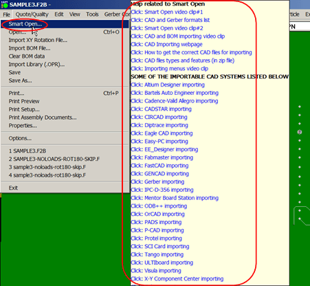
NOTE1: Later to open your own CAD files you can use the SMART OPEN feature which will automatically detect CAD files in a directory that can be imported into the Unisoft software. To use SMART OPEN click FILE off the main menu then click SMART OPEN and point to the directory that contains your CAD files and follow the instructions to display your PC Board assembly and other files such as AutoCAD drawing files.
You may import a Bill Of Material (BOM) and upon doing so the part number and descriptions contained in the BOM will be associated with the components on the display.
Click FILE on the main menu and click CLEAR BOM DATA then click IMPORT BOM
FILE. Make sure [DEFAULT] in the window displayed is selected. Click IMPORT and
select the file SAMPLE.BOM in the window displayed , then click OPEN. The BOM
importer window shows:
Warning: Duplicate BOM for REFDES 'U5'.
Totals: 28 items, 314 references. Complete.
0 components do not have part numbers
To illustrate the cross checking
the software does between the CAD file and BOM we have purposefully edited the
BOM to cause the message "Warning: Duplicate BOM for REFDES 'U5' ". For example
if U5 was socketed you could have U5 the socket and U5 the actual component part
in the same BOM and you would want this fact brought to your attention.
Click CLOSE to shut the window.
This applies only to Unisoft software versions older than 5.24.0.0. Windows users: If the BOM importing above was successful then please skip this step. If the BOM importing above did not perform as outlined then please follow this step and try the BOM step above again. On installation a file named markup.ini is copied to the c:\windows directory. This file helps to import the BOM. Windows security sometimes prevents the copying of this file. Please manually copy the markup.ini file located in c:\program files\unisoft or c:\program files (x86)\unisoft directory to the c:\windows directory. When you copy the file Windows will ask you if it's okay to copy it, answer yes. If the file is already there it is OK to overwrite it. Try the BOM importing step above again. Please call us (enable JavaScript for our phone number) if you need assistance.
Make sure the display is split and the left pane displays the top of the assembly and the right pane displays the bottom (this is the default display when the software first starts).
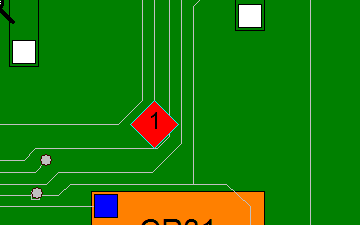
Click PLACE/AOI/X-Ray MODELS from the top menu. Click on MARK REFERENCE 1, the cursor will turn into a diamond. In the LEFT side pane move the cursor to the lower right of the assembly. Now place the cursor over a pin and click. The pin will turn to a diamond with the number 1 inside it (note that the REFERENCE 1 point selected is now the X=0 and Y=0 for the machine output file you will be generating). Click PLACE/AOI/X-Ray MODELS from the top menu. Click on MARK REFERENCE 2, the cursor will turn into a diamond. In the LEFT side pane move the cursor to the upper left of the assembly. Now place the cursor over a pin and click. The pin should turn to a diamond.
Important: Set
Reference 1 to the XY origin 0,0: For consistent results when exporting
your output files to set up your production equipment from the Unisoft software,
it is recommended that the Reference 1 point set using the Unisoft software also
be the XY origin 0,0 for the PCB. So for example, if you set the Reference 1
point on the top side of the PCB to be a fiducial point in the lower left corner
of the PCB and that point is not currently the 0,0 XY origin for the PCB, then
you can click on the PLACE/AOI... menu at the top of the Unisoft software, then
click SET ORIGIN, then click on the fiducial point where you put the Reference 1
point, and now that point will be the 0,0 for the PCB. If you are also
generating output file(s) from the Unisoft software for the bottom of the PCB
and the Reference 1 point you are choosing for the bottom is not currently the
XY origin 0,0 for the PCB, then repeat the previous process to set it to the XY
origin 0,0.
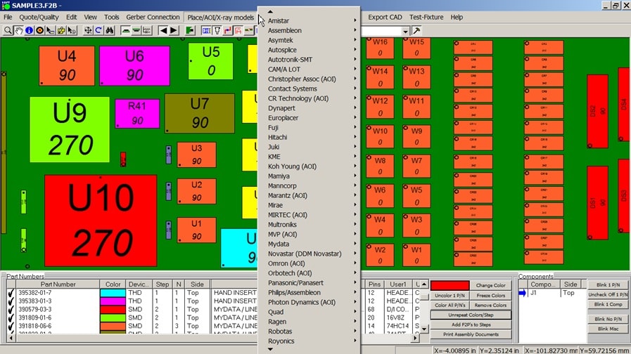
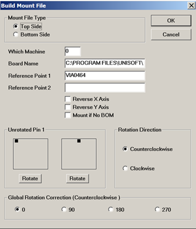
Click PLACE/AOI/X-Ray MODELS from the top menu then click MYDATA, then click on TPSys (note the older DIRECTLINE format is also supported). Next click OK and the BUILD TPSys FILE window opens. There are different options in this window to accommodate different machine and part types, including changing the 0 rotation of package types, global rotation correction, etc. ( for details clickhttps://www.unisoft-cim.com/manual-pronto-detail_mount-file-window.htm).
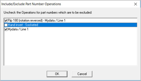
Click OK and then click SAVE and the INCLUDE/EXCLUDE PART NUMBER
OPERATIONS window opens. This window allows you to exclude any part number
Operations that you do not wish to be included in the output file. The
OPERATIONS notes in the figure below will not be in your window displayed
however for illustration in the figure below 3 Operation notes where added and
“Hand Insert – Socketed” is uncheck and would be excluded from the output
file. The OPERATIONS notes such as those in the figure below can be added using
several methods and will be detailed further in this manual and also can be
found at
https://www.unisoft-cim.com/library-overview.html .
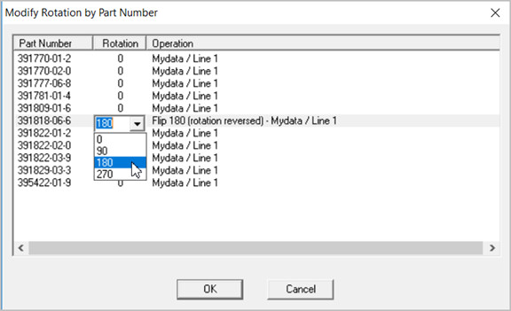
Click OK and the MODIFY ROTATION BY PART
NUMBER window opens. This window allows you to modify the rotation of a part
number created in the output file. For example you may need to flip 2 pin
polarized components such as diodes and LEDs 180 degrees. The rotation change
is in the output file only and does not affect the displayed PCB. For any one of
the part numbers displayed click the 0 under the Rotation field for that part
number and add any rotation you wish. Note the rotation is added to the existing
rotation so for example adding 90 degrees to a component at 180 degrees results
in 270 degrees in the output file.
The OPERATIONS notes in the figure
below will not be in your window displayed however for illustration in the
figure below several Operation notes where added and for “FLIP 180 (rotation
reversed)…” 180 degrees of rotation was added for that part number in the output
file created. The OPERATIONS notes such as those in the figure below can be
added using several methods and will be detailed further in this manual and also
can be found at
https://www.unisoft-cim.com/library-overview.html .
Click OK. Note the amount of components that were placed in the message
window. Click CLOSE.
The file just created is called SAMPLE.PCB. You can
view SAMPLE.PCB with any editor in the directory you saved it to ( the
SAMPLE.PCB you just created should be in the directory c:\program
files (x86)\unisoft or c:\program files\unisoft ). SAMPLE.PCB
contains the top side component placement information compatible with the MYDATA
/ MYCRONIC assembly equipment. The MYDATA / MYCRONIC machine then takes this
file as input and you are ready to assemble the top side of the board.
MYDATA / MYCRONIC .MNT MOUNT FILE SAMPLE:
F1 SAMPLE
U 1
F3 -153670 -3810 FID1
F3 6350 49530 FID2
F6 0 0
F7 0 0
F8
-137160 8890 90000 0 N N 390579-03-3
F9 U10
F8 -144145 34290 90000 0 N N
390607-01-0
F9 U9
F8 -128905 38735 270000 0 N N 391770-01-2
F9 R41
Note: When panelization is needed this is done directly on the
MYDATA / MYCRONIC machine. However for other assembly machines on the Unisoft
software a separate panelization window will appear with the offset coordinates
entries for each panel.
Note: Mydata / Mycronic component rotations can differ from the normal used on most other assembly machines. For more details on how to adjust for Mydata rotations please go to https://www.unisoft-cim.com/mydata-rotations.html.
Note that we have used the Mydata / Mycronic assembly machine for our example
above. Please feel free to create output for any one of the many assembly
machine models listed in the main menu pull down "PLACE/AOI/X-Ray MODELS". The
procedure for the other machines listed there is straight forward and similar to
the Mydata / Mycronic output we just created.
The Unisoft software
supports virtually all SMT & THT assembly machine makes and models both new and
old. For example Assembleon / Philips, Mydata / Mycronic, Juki, ASM / Siemens,
Universal, Fuji, Siemens, Contact Systems, Samsung, Quad, Europlacer, Sanyo,
Sony, Panasonic, Mirae, Essemtec, Yamaha, Hitachi, MultiTroniks, Amistar,
Manncorp, Robotas, Autoronik-SMT, Dima, Dynapert, KME, Zevatech, Mamiya,
Novastar, Ragen, TDK, Tenyru, Tescon, TWS Automation, Dynapert, etc.
Below are a few sample Assembly Machine setup file formats created by the
Unisoft software.
RefDes PartNumber Shape X Y
Rotation Layer
U1 391818-06-6 SOIC14 0.150 0.150 90 TOP
U2 391818-06-6
SOIC14 -0.700 7.325 0 TOP
U3 391818-06-6 SOIC14 -0.200 7.325 0 TOP
IC4
360-0834 90 1.575 1.475
R24 111-0122 270 2.750 3.200
R26 111-0103 270
2.250 3.200
C1= ( 391777-06-8,1206,,,-121.92,6.35,270,TOP)
R2= (
391770-02-0,SOM16,,,-99.06,53.98,90,TOP)
U11= (
395422-01-9,SOIC8,,,-87.00,53.98,180,TOP)
Contact Systems – CS400
206"242432-03"
004+0000+0000+0000+0000
002+0000+0000+0000+0000
012+0004+0000+0000+0000
116+0000+0000+0000+0000
216"BIN 1"
010-0159+1432+0000-0160\R1 \
012+0004+0000+0000+0000
216"BIN 2"
010-0199+1432+0000-0160\R2 \
(Note: Skip to the step below "HOW TO TUTORIALS" if you used the GERBER sample data because the GERBER sample data does not have bottom side components).
Click PLACE/AOI/X-Ray MODELS from the top menu. Click on MARK REFERENCE 1, the cursor will turn into a diamond. In the RIGHT side pane move the cursor to the lower right of the assembly. Now place the cursor over a pin and click. The pin should turn to a diamond. Note that the REFERENCE 1 point selected is now the X=0 and Y=0 for the machine output file you will be generating. Click PLACE/AOI/X-Ray MODELS from the top menu. Click on MARK REFERENCE 2, the cursor will turn into a diamond. In the RIGHT side pane move the cursor to the upper left of the assembly. Now place the cursor over a pin and click. The pin should turn to a diamond.
Click PLACE/AOI/X-Ray MODELS from the top menu then click MYDATA, then click
on TPSys and click OK. In the Build TPSys File window displayed click the BOTTOM
SIDE button at the top of the window. Next click OK and then in the File Name
field change the name to SAMPLEB.PCB and click SAVE and the INCLUDE/EXCLUDE PART
NUMBER OPERATIONS window opens and then click OK and the MODIFY ROTATION BY PART
NUMBER window opens then click OK again. Note the amount of components that were
placed in the message window. Click CLOSE.
The file just created is
called SAMPLEB.PCB. You can view SAMPLEB.PCB with any editor in the directory
you saved it to ( the SAMPLEB.PCB you just created should be in the directory
c:\program files (x86)\unisoft or c:\program files\unisoft ) . SAMPLEB.PCB
contains the bottom side component placement information compatible with the
MYDATA / MYCRONIC assembly equipment. The MYDATA / MYCRONIC machine then takes
this file as input and you are ready to assemble the bottom side of the board.
Note1: When doing
your own PCB assembly ( PCBA ) using the Unisoft software it is recommended that the MARK
REFERENCE 1 point for the bottom side of the PCB assembly ( PCBA ) be located on the bottom
right corner of the board when viewed in the Unisoft software. Also it is
recommended that the point that is chosen for MARK REFERENCE 1 on the
bottom side is also set to the XY 0,0 origin of the PCB assembly ( PCBA ) using the SET ORIGIN
feature.
By doing this the coordinates displayed for the
components in the Unisoft software will typically be the same as the coordinates
exported to the file to program the assembly machine making verification, if
needed, easier. Also the PC board will then usually be located in the first
quadrant where the component coordinates (x;y) will both be positive.
Note2: When viewing
the bottom side of the PCB assembly ( PCBA ) in the Unisoft software the board is actually viewed
flipped and therefore the X coordinates are more positive as they go from right
to left. This is the opposite of viewing the top side of the PCB assembly ( PCBA ) in the Unisoft
software where X coordinates are more positive as they go from left to right.
For this tutorial we will open a PC Board with additional annotation notes and steps we have previously added. From the main menu click FILE click OPEN, click CONTINUE and select the file SAMPLE3.F2B and click OPEN and click NO in the "Save Changes to sample" window. The PC Board is displayed and click CLOSE in the "Messages from importer module" window.
There are over a 100 features of the Unisoft basic software module ProntoVIEW-MARKUP below are a few example tutorials.
Note: More detail, an
overview and other links for creating assembly documents, assigning Steps and
Substeps, Coloring components, adding annotations, etc. can be found at
https://www.unisoft-cim.com/assembly-docs-how-to-create-sample.html .
The Unisoft software allows you to quickly create matching assembly lists and assembly drawing sheets for each step in the assembly process. Part numbers are automatically assigned to the assembly step you wish (for example: Step 1 for Hand Inserts, Step 2 Chip Shooter components, etc). The part numbers are then automatically uniquely colored. If needed, overlay annotation notes can be added to each step. Next for each step matching assembly lists and assembly drawings are created. These drawings can either be printed or saved to a file (PDF Adobe, etc.) or displayed on the screen.
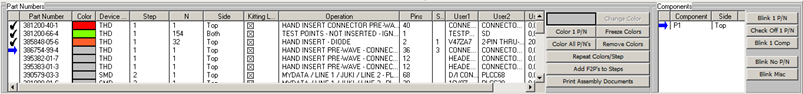
To create assembly and process sheets on the main menu click ASSEMBLY SHEETS/1st ARTICLE then click OPEN SMART COLOR OPERATIONS and a new window appears at the bottom.
The SMART COLOR window at the bottom is sortable either by Part Number, Step Number, N=number of components for that part number, Operation, number of Pins on the component, etc.
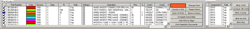
To assign an Operation to each part number from the main menu click EDIT then BOM then IMPORT LIBRARY (.OPR) and a new window will appear. In the window click on the file SAMPLE.OPR to select it then click OPEN. The result is that under the OPERATION field at the bottom of the screen each part number has been automatically assigned a operation step, for example Part Number 390579-03-3 is assigned Operation "Mydata / Mycronic AUTO INSERT".
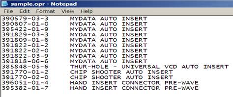
The Operation field is optional and it is easily populated by the .OPR file which is a simple text file. The .OPR file contains the Part Number followed by a tab then the Operation text for that part number (Example: 396051-01-4 HAND INSERT SOCKET PRE-WAVE). The Operation information in the .OPR file is automatically assigned to every part number on the assembly. The SAMPLE.OPR file used in our example is located in the directory by default c:\program files\unisoft or c:\program files (x86)\unisoft . Also the Operations can be manually entered by double clicking on the Part Number and editing the OPERATION field directly in the window provided. Then you can export and save the Operation information you have manually entered to an .OPR file by clicking EDIT then BOM then EXPORT P/N operation.
(NOTE: This exported file does not append to an existing .OPR file. It simply exports the Part Number and Operation field to a new file. Of course if you wish at that point you can manually append that file to another existing .OPR file.)
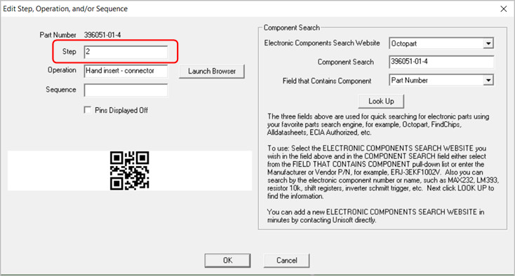
In the bottom window to the right of the PART NUMBER field you will find the STEP field. In this field you may optionally add STEP NUMBERS to part numbers in order to create separate unique steps in the PC Boards assembly process (for example: Step 1 for Hand Inserts, Step 2 Chip Shooter components, etc). To assign a STEP NUMBER to a part number at the bottom of the display double click on a part number and edit the STEP field with a step number. When the PC Board and BOM are first imported all steps are defaulted to step 1. Note that we have previously added step numbers 1 through 5 for our sample PC Board.
(Note for creating .F2P files: The .F2P files are where annotation overlays can be saved and stored for reuse. The .F2P files can contain 1 or more annotation overlay. These .F2P files can be imported for display into any PCB assembly ( PCBA ) in the Unisoft software and used simply for display or as part of the assembly process steps in the assembly documentation creation. For details on how to create .F2P files go to F2P-FILES.)
If needed overlay annotation notes can be added to each process step. To do this click ADD F2P'S TO STEPS.
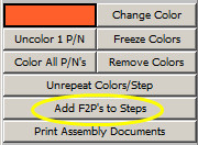
The following window appears!
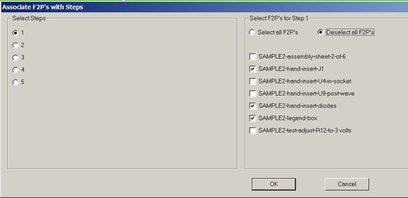
For our sample board we have previously created five process steps. Now for each one of these steps we can optionally add .F2P annotation overlay notes. In the figure above for example Step 1 is selected on the left and on the right 3 .F2P overlays boxes are checked. These four overlays will be printed on top of the PC Board display for step 1. The results would look something like the figure below. Please click on step 2 through 5 on the left side and you will see the .F2P overlays that will be printed for those steps.
(NOTE: The sample PC board we are working with already has 7 .F2P annotation overlays pre-loaded into it. It is not necessary now but in the future to add F2P Annotations to the Window above you need to Load them first. To Load Annotations from the Main menu click EDIT, click ANNOTATIONS then click LOAD ANNOTATIONS and select the .F2P file you wish to load then click OPEN.)

In the window at the bottom click the COLOR ALL P/N's button. The "select Components" window below opens. Put check marks in this window the same as illustrated below and then click OK.
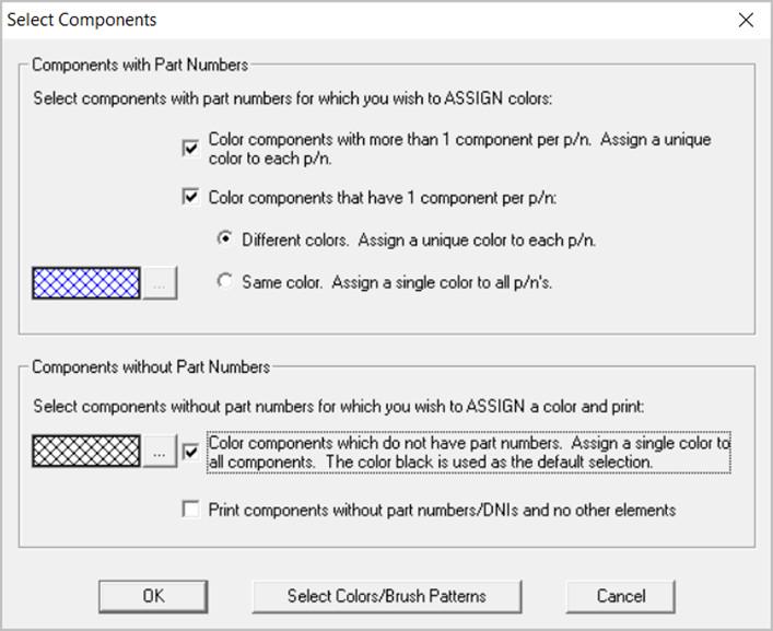
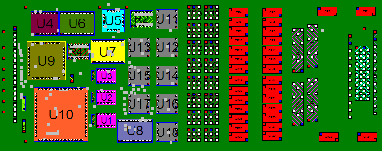
The result is that each part number and the components associated with that part number have been assigned a unique color and pattern according to the sort sequence of the part numbers in the SMART COLOR window at the bottom of the display. You also have the option to repeat the color sequence for each Step Number in the process. To do this in the window at the bottom click the REPEAT COLORS/STEP button and the colors on the PC Board will change. Note the same color will appear for different part numbers because these part numbers are in different steps. Click the UNREPEAT COLORS/STEP button again to toggle the colors to their previous state.
To freeze the colors that are currently applied to the part numbers click the FREEZE COLORS button located in the center right of the SMART COLOR window then click YES in the window that appears. Click UNFREEZE COLORS to unfreeze the colors applied to the part numbers.
The assembly instructions for this PC Board are now complete. For this PC Board we have previously added 5 process STEPS. To Print Assembly Sheets and matching Assembly Load Lists for each process step in the window at the bottom of the display click the button PRINT ASSEMBLY DOCUMENTS.
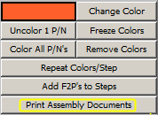
The following window is displayed!
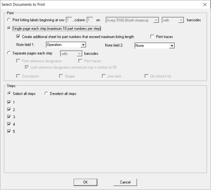
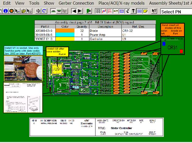
There are two options for printing Assembly Documents SINGLE PAGE EACH STEP and SEPARATE PAGES EACH STEP. The first option SINGLE PAGE EACH STEP results in a document that looks like the one below where each Step in the assembly process is printed on one sheet for each side of the PC Board assembly. Note in the figure below that the load list of the components to be inserted at that step are listed by part number at the top of the same sheet with the PC Board assembly under it and on the PC Board the components to be inserted at this step are colored with matching colors to the load list above it.
To print this drawing below in the window above under PRINT select SINGLE PAGE EACH STEP and under STEPS select select ALL STEPS. Next click OK and select the printer or PDF file you wish to print to and Click OK and the document will be printed.
Note: The check box above "Create additional sheet for part numbers that exceed maximum listing length" if checked will add an additional sheet for any part number with more components then will fit on the single sheet printout. Also NOTE FIELD 1 above is selectable to display the various data fields available and the data in that field will be displayed in the 4th column as in the figure below. NOTE FIELD 2 above can be optionally selected to be displayed and can also display the various data fields available. If NOTE FIELD 2 is selected the 4th field below will be split in half and NOTE FIELD 2 will be the 5th field.
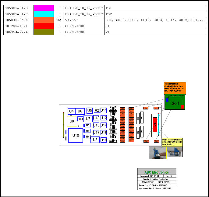
The second option for printing assembly documents is SEPARATE PAGES EACH STEP which results in a document that looks like the two figures below. The assembly drawing and the load list for each step are on separate sheets and this allows for additional space to print more information on the load list. Note in the two figures below that the load list of the components to be inserted is on its own sheet and the PC Board assembly drawing is also on its own sheet. The load list and PC Board assembly drawings have color matching components to be inserted at this step.
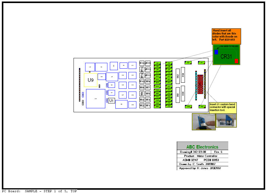
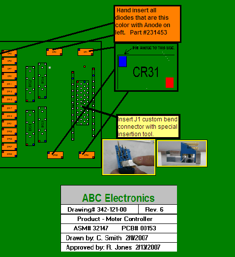
Note in the two drawings above that in the second drawing which is Assembly Sheet #1 of 5, CR1 to CR32 are colored green. Also printed are the 3 .F2P annotation overlays selected earlier for step 1 including "Hand insert all diodes that are this color", "insert J1 custom bend connector", and the legend box "ABC Electronics". In the first drawing above which is the matching Assembly Load List Sheet #1 of 5, the third item is part number 385-848-05-6 which are components CR1-CR32 and for this item we have included automatically the part number, the operation text "hand insert diodes", the quantity of 32, the device type THD, the component part number color of green, and optionally additional Bill Of Material (BOM) information of tolerance/package/description and top side reference designate listings of CR1 through CR32.
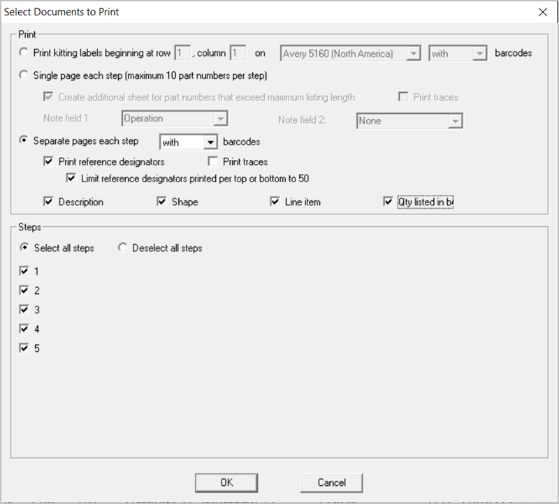
To print the drawings above at the bottom center of the main display click the button PRINT ASSEMBLY DOCUMENTS and the window below appears. Under PRINT select SEPARATE PAGES EACH STEP and then put a check mark in all the 6 boxes located under SEPARATE PAGES EACH STEP. Next under STEPS select select ALL STEPS. Then click OK and select the printer or PDF file you wish to print to and Click OK and the document will be printed.
The Unisoft software allows you to quickly create Kitting Labels with barcodes for fast and accurate electronic component kitting. Quickly select the component part numbers for which you wish kitting labels created. Each label contains the part number, unique part number color, step number, p/n description, reference designator, etc. Fast and easy electronic kitting labels for kitting work orders.
Barcodes of various types can be printed on the kitting labels and shown on the display for quick kitting,
fast assembly machine feeder loading, verification, inspection, etc.: 2d-qr code, 2d-data matrix, etc.
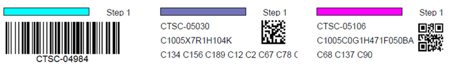
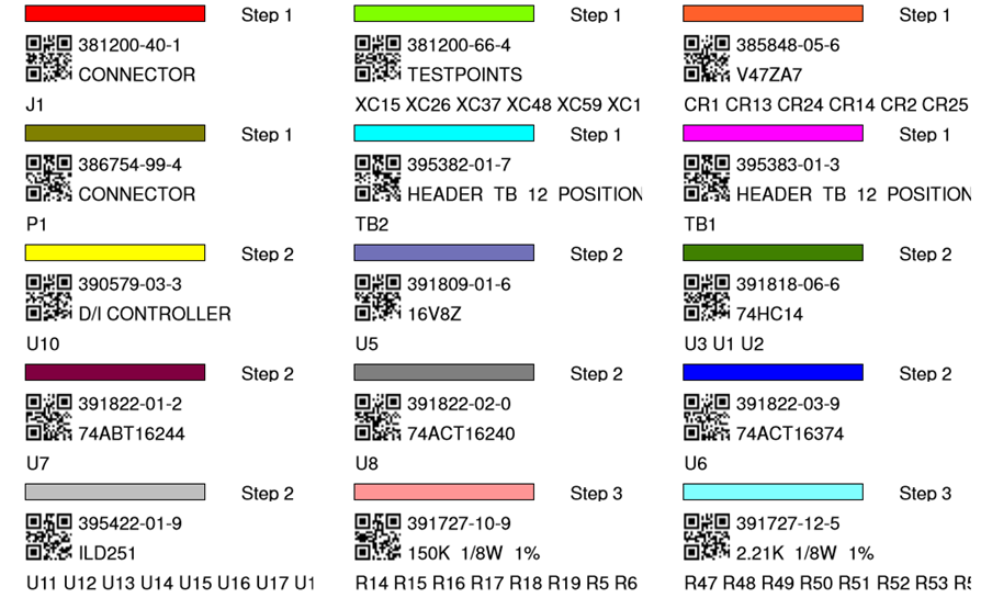
To use this feature the Smart Color window should be open at the bottom of the display and there you will see the field KITTING LABEL. By default all the thru hole component Part Numbers under the KITTING LABEL field are checked. All checked component part numbers will be included in the Kitting Label to be printed. You may add and remove checks as you wish.
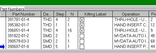
To print the Kitting Labels for the checked part numbers click PRINT ASSEMBLY DOCUMENTS at the bottom middle of the display. Next select the PRINT KITTING LABELS button and click OK and OK again and if asked select the barcode type then click OK and select your printer output.
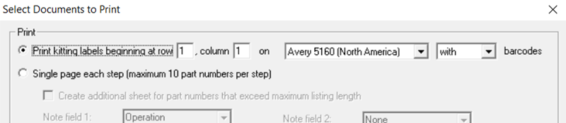
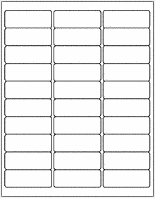
The labels created by default are standard Avery 5160 type (30 labels — 3 across & 10 down).
(Note for creating .F2P files: The .F2P files are where annotation overlays can be saved and stored for reuse. The .F2P files can contain 1 or more annotation overlay. These .F2P files can be imported for display into any PCB assembly ( PCBA ) in the Unisoft software and used simply for display or as part of the assembly process steps in the assembly documentation creation. For details on how to create .F2P files go to F2P-FILES.)
Additional text and graphics can be added to the Assembly by creating .F2P annotation overlays. To add annotation notes to the assembly similar to the figure below click the Annotation Tool button  on the top toolbar. Your cursor will change to
  .
.
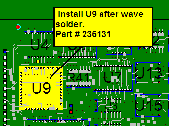
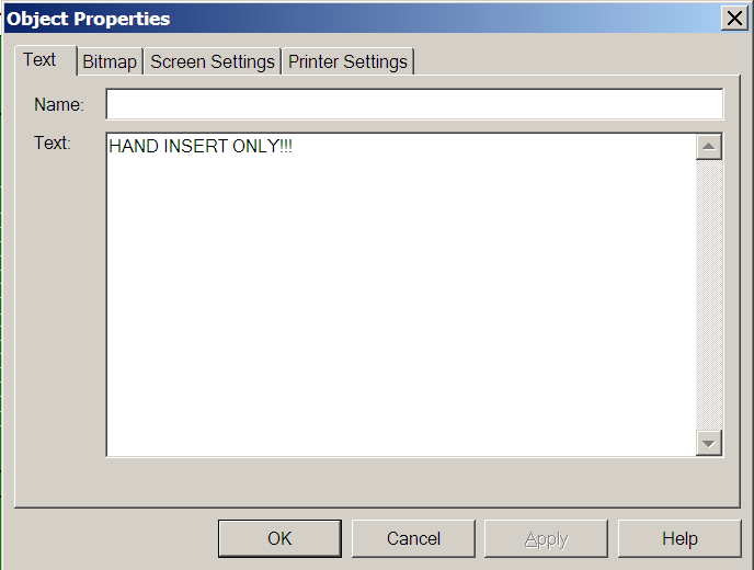
Drag a rectangle within a top or bottom view window. Release the mouse button after dragging your rectangle. The tabbed Object Properties dialog opens. This is where you can specify properties for your annotation.
Click the TEXT tab (if necessary). In the Text box, type the text you want to appear in the annotation. Click OK. The display contains the annotation.
With the Annotation Tool selected, click the annotation you just added. A shortcut menu appears.
Click Call Out. A callout line appears to the right of the annotation. With the annotation cursor, click and hold the tip of the callout. Drag the callout to the desired location. While you drag, a thick line will stretch from the center of the annotation to the tip of your cursor. Note: If the tip of the callout is not in view, you may have to use the panning tool (TOOLS / PANNING TOOL) to move it into view. Release the mouse button. The callout line will move to the desired location.
Click and drag the annotation to the desired location and note that the other end of the callout has not changed its anchor position.
Line draw tool: To create a line use the Line Draw tool by clicking the Annotation Tool button on the top toolbar until you see this icon
 with a vertical line on the left side of the yellow note then you are in the Line Draw mode. Similar to annotations, if you left-click on the line, you have the choice of deleting the line or changing its properties.
The CHOOSE F2P'S TO DISPLAY window allows you to turn on and off individual F2P annotation overlays that have been loaded.
Click the ANNOTATIONS icon  at the top of the display (it is the 3rd icon in from the right) and the "CHOOSE F2P'S TO DISPLAY" window below appears.
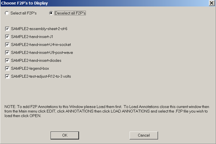
Our sample SAMPLE3.F2B file we are working with has the 7 sample .F2P Annotation overlays listed in the window above already loaded into it. These same 7 .F2B files are also on the directory by default c:\program files\unisoft or c:\program files (x86)\unisoft. The list of the 7 F2P's are in the figure above starting with SAMPLE2-assembly-sheet-2-of-6.f2p. Feel free to load and unload them as you wish to get a feel for this feature.
NOTE: When you first start a new project no F2P annotations will appear in the window above. To add F2P Annotations to the Window above you need to Load them first. To Load Annotations from the Main menu click EDIT, click ANNOTATIONS then click LOAD ANNOTATIONS and select the .F2P file you wish to load then click OPEN.
The CHOOSE F2P'S TO DISPLAY feature is also in the included viewer software so for example in the figure below an assembly person on the production floor can select the HAND INSERT overlays to help guide them with assembly.
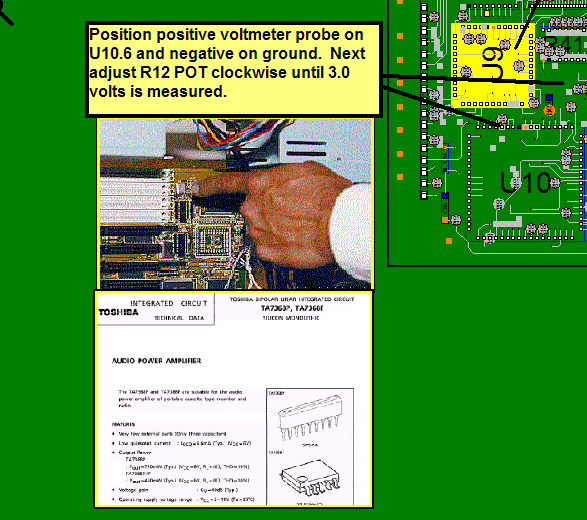
Or as in the figure below PC Board Test personnel can use the included viewer software to select the SAMPLE2-test-adjust-r12-to-3 volts.f2b overlay to guide them with a test setup procedure.
The ProntoVIEW-MARKUP included cad viewer & Gerber Viewer software can display these results for assembly personnel at their computers on your production floor or if you do not have computers they can be printed for exact assembly instructions, for example (PART NUMBER / OPERATION / NUMBER OF PARTS / COLOR).
Generally First Article Inspection is done on the first PC Boards assembled. When the assembly inspection is satisfactory at that point the PC Board can be built reliably in quantity.
After completing the tutorial above in the lower left of the SMART COLOR window at the bottom right of the display click REMOVE COLORS. In the window that opens click OK. The result is all component coloring is now cleared. Now single click the first part number displayed in the SMART COLOR window at the bottom under the "PART NUMBER" field. Then click BLINK 1 P/N located on the right side of the SMART COLOR window. This will blink those components with that part number. In real life the person doing the First Article Inspection would check each of those components for the correct part number installed. If all components with that part number are correct then they would check off that part number to indicate it is correct. Please do this now by clicking CHECK OFF 1 P/N located on the right side of the SMART COLOR window. Note a check mark has been inserted to the left of the part number indicating it has been completed and also a color has been inserted to the right of the part number in that same color has been applied to components with that part number on the displayed PC board. The inspector would continue this process for each part number until all part numbers are checked off and colored at which point that would indicate all components on the PC Board have been assembled correctly. At that point the PC Board can be built in quantity as needed.
This feature of Blinking and Coloring by part number can also be used for other production floor operations. For example for hand assembled components the operator can select the part number they are assembling by clicking that part number displayed in the SMART COLOR window at the bottom under the "PART NUMBER" field. Then click BLINK 1 P/N located on the right side of the SMART COLOR window. This will blink those components with that part number. At that point the person would assemble those components that are blinking. After all components with that part number are installed then they would check off that part number to indicate it has been installed by clicking CHECK OFF 1 P/N located on the right side of the SMART COLOR window. At that point a check mark has been inserted to the left of the part number indicating it has been completed and also a color has been inserted to the right of the part number in that same color has been applied to components with that part number on the displayed PC board. The hand assembly personnel would continue this process for each part number they are installing by hand.
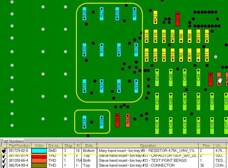
Note: Many customers that use this feature of Blinking and Coloring by part number for slide line hand assembly add additional instructions for the assembler in the Operations Field (see figure below). For example:
"Mary hand insert - bin tray #8 - RESISTOR 4.75K_1/4W_1% - p/n-391729-02-0"
Information such as this can be easily added automatically via the Operations Library or manually inserted.
Using the FIND feature allows you to find a component or component pin. You can find a net trace or 2 net traces to identify where a short between two traces maybe. Search and find by netname or by part number. Also find by description field from the Bill Of Materials (BOM), for example find all "0.1uf capacitor". You can also find a Test Probe X/Y location and Test Probe number for your Bed Of Nails test fixture.
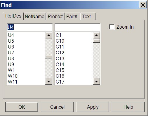
To open the FIND window either at the top of the display click the FIND icon  or from the main menu click EDIT then FIND. Next to search for a component type U4 in the top left field and click APPLY. The result is the cursor moves to U4 and U4 is highlighted in red. Note that APPLY finds what you are looking for and leaves the FIND window open for further finds or clicking OK closes the FIND window and locates the item you requested.
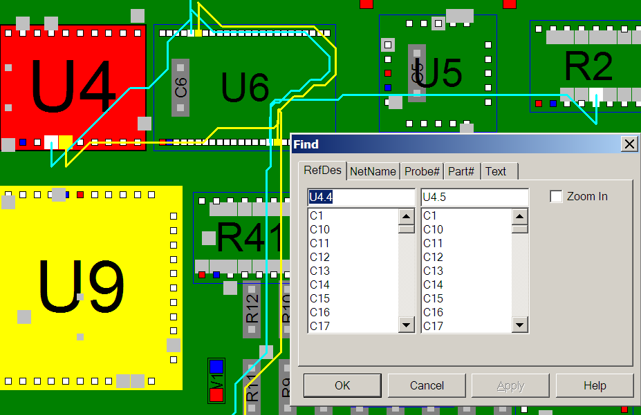
To locate a short between two traces in the FIND window in the top left field type U4.4 and in the top right field type U4.5 and click APPLY . Note as in the figure below the two traces in question are highlighted. One trace is in yellow and the other blue. A technician would then follow along the two traces and where they came closest to each other would be the most likely place to find the short.
Choose any of the other tabs to experiment with the different types of search options available. Click CLOSE to close the FIND window.
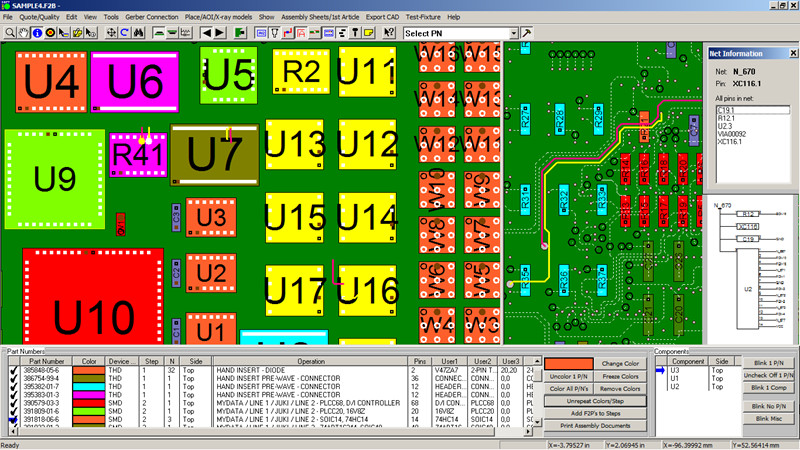
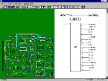
Click VIEW from the main menu then click RIGHT PANE. Click VIEW again then click SCHEMATIC. The right pane now displays "No Net selected". Click VIEW from the main menu then click LEFT PANE and select a net by either clicking the select tool (Bull's-eye icon) then clicking on a pin on the display or using the Find feature to select a net. The result is the schematic should be displayed in the right pane. The schematic view in the right pane is also an active display so by clicking any signal name or pin number on the right side on the components displayed will now navigate to that signal. You can now navigate any signal down its resultant path.
For further details on features and operations please review the manuals by clicking the "ProntoVIEW-MARKUP VIEW Manual" icon and clicking the "ProntoVIEW-MARKUP MARKUP Manual" icon in the Unisoft folder.
You will want to save your work initially or after adding annotations to your file. You can save your work as a .F2B file (complete board save) or as a .F2P overlay file (saves only annotations you have added).
To save as .F2B — On the FILE menu, click SAVE.
Note: If you want to save the file with a different name, on the FILE menu, click SAVE AS. The Save dialog box appears. Type a name in the FILE NAME box. Click OK.
An .F2B file contains all of the board information, plus the annotations. The board file is loaded first and then the annotation file is loaded on top of the board file. When you save the file, the system defaults to the original file name with a different extension. This file can be viewed by anybody using the VIEW-MARKUP software or any of the other Unisoft software modules. If you plan to send your annotated board along with the included VIEW-MARKUP program to another person, the F2B file is more convenient.
To save a .F2P overlay file — Click EDIT from the main menu, then click ANNOTATIONS and SAVE ANNOTATIONS. The Save dialog box appears. Type a name in the FILE NAME box. Click OK.
An .F2P file contains just the annotations you have added to the PC Board assembly display such as component coloring, notes and graphics. The .F2P can be viewed in conjunction with an .F2B or CAD files at a later time. If you want to develop multiple visual aids based on the same CAD file, or if you receive updated CAD files in the future, it is better to save F2P files. These files can then be loaded against the similar or updated PC Board design saving you the time of recreating the annotations. F2P's can be overlayed individually or stacked in combination.
All Pronto software modules have all the features found in the ProntoVIEW-MARKUP software and are compatible with MARKUP.EXE no charge PCB assembly ( PCBA ) CAD Viewer & Gerber Viewer Software. Normally this CAD Viewer & Gerber Viewer is used throughout the plant floor or given to vendors or clients for better communications. The CAD Viewer & Gerber Viewer has over 100 features that make it the ideal ONE TOOL for the various departments of a typical electronic manufacture. Features include viewing and printing out of the display, find by Reference Designator, Part Number and more. To give the included cad viewer & Gerber Viewer to someone simply send them the MARKUP.EXE and the .F2B file for your PC Board (MARKUP.EXE is usually located in the c:\program files\unisoft or c:\program files (x86)\unisoft directory).
To open your own cad files you can use the smart open feature which will automatically detect cad files in a directory that can be imported into the Unisoft software.
To use SMART OPEN click FILE off the main menu then click SMART OPEN and point to the directory that contains your CAD files and follow the instructions to display your PC Board assembly.
The Unisoft software imports the standard ASCII file that CAD systems create. Each CAD system has its own format. To view a variety of the latest full CAD samples please see directory c:\program files\unisoft\data-files or c:\program files (x86)\unisoft\data-files and look for the files starting with SAMPLE_. For example you will find SAMPLE_PADS.ASC which is the PADS CAD systems ASCII output file. This and the other sample CAD files can be directly imported into the Unisoft software. Simply match your file to one of the samples and your PC-BOARD can be displayed with the Unisoft software.
An API function for external control is included if you need to operate the Unisoft software from your application or equipment.
The API is contained in the file REMOTEAPI.ZIP in the directory …\unisoft where you installed the software. Please unzip this file into the …\unisoft directory. The result should be directories …\unisoft\remoteapi\rapi_test.
See the file README.TXT in the directory …\unisoft\remoteapi\rapi_test on how to use the API. Also the files API.H and RAPI_TEST.C explain the functions.
ShowCurView
ZoomCurView
OpenBoard
SetCurView
ShowCurView
ZoomCurView
Rotate
Flip
MoveCurView
ClearBom
ClearAnnotation
ImportBom
ImportAnnotation
FindComponents
FindNets
We have supplied a function tester program. You can test out the functions by running RAPI_TEST.EXE in directory RAPI_TEST. See the readme above for details.
For example, run RAPI_TEST.EXE and type HELP to get general help or type HELP FindComponents to get specific help for FindComponents. If you type FindComponents 1 U11, the 1 will zoom the display to where U11 is located and component U11 will be highlighted. If you type FindComponents 1 U11.3 U6.9 then both the component U11.3 and U6.9 pins and traces will be highlighted.
RAPI_Test — contains samples of how you can use the API via a DOS prompt.
Please note that when using the DOS command prompt test program — if you type Help at the command prompt (Enter>) you will get a list of all the API functions available to you. If you type 'help' and then the functions name (e.g., Enter>help OpenBoard) it will explain how to use that particular function. You should go through this tutorial to become familiar with the functionality of the API.
If you review the C code in the file (RAPI_Test.c) you will see how the actual DOS prompt program was written. You can write similar functions in your own code that will call up the program and launch the necessary API functions you wish.
Additional details on the Unisoft software features can be found on the Features page.
If you chose the default path on installation the software was installed to the directory c:\program files\unisoft or c:\program files (x86)\unisoft. The executable program for the Unisoft software is MARKUP.EXE. The Icons group are installed in the PROGRAM GROUP under the Unisoft folder. Also shortcuts to the software and this quick start manual have been placed on your desktop.
Thank you for evaluating the Unisoft software. Please call us (enable JavaScript for our phone number) or email us (enable JavaScript for our email address) with any questions.