(Quick Start Manual addendum)
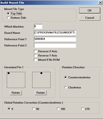
The "BUILD xxx FILE" window above is normally displayed in the process of creating your machine file output with the Unisoft software. This windows name may vary slightly depending on the output machine file being created (for example: BUILD MOUNT FILE or BUILD TPSys FILE). Except for selecting either to build the TOP or BOTTOM side machine file normally it is not necessary to change anything in the "BUILD xxx FILE" window. However, when needed, if the data being imported is not correct, then this window can modify rotations, reverse the X and Y axis, etc. Below are details on each field. Please contact Unisoft directly if you wish online training for this feature.
Note: The WHICH MACHINE feature above is no longer available. Alternative methods for splitting a PC Board into multiple machine outputs have been created. Please contact Unisoft for details.
UNROTATED PIN1: The left side box in this field indicates the zero degrees rotation for IC type packages 4 pins or greater (also 3 pin in-line packages) and only affects SMD components. The default for the left side box is 0 degrees rotation = top of the device package. And this applies to packages with pin 1 in the top left or packages with pin 1 in the middle of a row such as on PLCC's.
For example U63 is 270 degrees on the display above and with the default setting (see image below) the result is that in the assembly file created U63 will be 270 degrees when the Rotation Direction (see further, below) is set to CCW.
If you click ROTATE once it changes the pin one 0 degrees position by 90 degrees and the result is that in the assembly file created U63 will be 180 degrees when the Rotation Direction (see image below) is set to CCW.
Note: If the UNROTATED PIN 1 box controls do not seem to be changing the rotations in the output file created than most likely you have a fixed rotation CAD file type that was imported. To resolve this issue please go to the "1) RESET ROTATION FEATURE" section on the Rotation modification options page.
UNROTATED PIN1: The right side box in this field indicates the zero degrees rotation for 3 pin packages only such as transistors (excluding 3 pin in-line packages).
The default for the right side box is 0 degrees rotation = the pin 1 top of the device package.
So for example below D3 is displayed as 270 degrees and if you wish 180 degrees instead in the output assembly file then click the ROTATE once.
D3 is 270 degrees on the display (see image above) and with the default setting (see image below) D3 will be 270 degrees in the assembly file created when the Rotation Direction (see further, below) is set to CCW.
If you click ROTATE once it changes by 90 degrees the CCW rotation and the result is that in the assembly file created D3 will be 180 degrees when the Rotation Direction (see image below) is set to CCW.
If for example for an IC component package the 0 degrees rotation is set to when pin 1 of the device is in the upper left corner
and the if a component of that type is placed on the PCB assembly ( PCBA ) with pin 1 in the lower left corner
then if the Rotation Direction is set to CCW
then the rotation of the component in the machine output file being created will be 90 degrees.
Example:
391728-10-9 U6 -5.500 -1.225 90.0 TOP
If the Rotation Direction is set to CW for example as it is by default with Mydata / Mycronic assembly machines
then the rotation of that same component in the machine output file being created will be 270 degrees.
Example Mydata / Mycronic file:
F8 -129540 52070 270000 0 N N 391822-03-9
F9 U6
Please contact Unisoft directly for further detail.
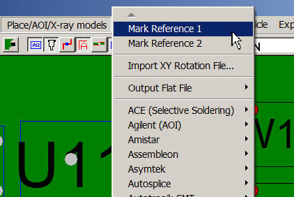
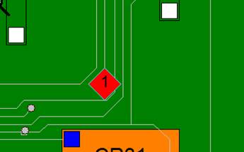
When generating the output files to program your production floor equipment the relationship of the component XY CENTERS, REF 1 and ORIGIN 0,0 of the PCB assembly ( PCBA ) using the Unisoft software is as follows:
Contact Unisoft directly for additional details.