SUBJECT: Mydata / Mycronic assembly equipment origin & rotation settings, issues, etc.
Software version:
For stability with the Unisoft exports for
Mycronic/Mydata machines with component rotations, etc. it is recommended that
the Unisoft markup.exe software version 5.25.5.0 or
newer be used.
With this version of
the software normally no special settings are required when generating the
output file to program the Mycronic/Mydata machines.
To check the version of the software you are using from the main menu click
HELP then ABOUT. The latest version download can be found
here .
Setting the XY
origin:
Set Reference 1 to the XY origin 0,0: For consistent results when
exporting your output files to set up your production equipment from the Unisoft
software, it is recommended that the Reference 1 point set using the Unisoft
software also be the XY origin 0,0 for the PCB. So for example, if you set the
Reference 1 point on the top side of the PCB to be a fiducial point in the lower
left corner of the PCB and that point is not currently the 0,0 XY origin for the
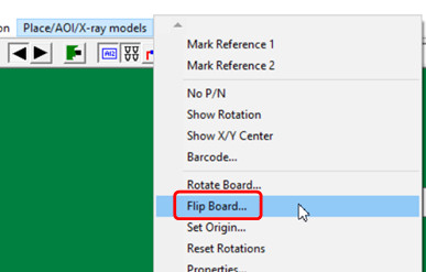
PCB, then you can click on the PLACE/AOI... menu at the top of the Unisoft
software, then click SET ORIGIN, then click on the fiducial point where you put
the Reference 1 point, and now that point will be the 0,0 for the PCB. If you
are also generating output file(s) from the Unisoft software for the bottom of
the PCB and the Reference 1 point you are choosing for the bottom is not
currently the XY origin 0,0 for the PCB, then repeat the previous process to set
it to the XY origin 0,0.
Below are a number of special setting options
when generating the output file to program the Mycronic/Mydata machines.
Again note for stability with the Unisoft exports for
Mycronic/Mydata machines with component rotations, etc. it is recommended that
the Unisoft markup.exe software version 5.25.5.0 or
newer be used. With this version of the software normally no special
settings, like those outlined below, are required when generating the output
file to program the Mycronic/Mydata machines.
If the markup.exe software version 5.21.0.0 or newer is used then you would normally use the default rotation settings that the software uses when creating your Mydata / Mycronic assembly programming file and not the settings outlined below. To check the version of the software you are using from the main menu click HELP then ABOUT. For Unisoft software markup.exe versions 5.20.xx and older use the rotation settings outlined below.
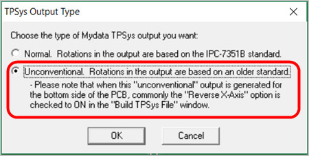
The Mydata / Mycronic electronics PCB assembly ( PCBA ) machines tend to be somewhat unusual compared to other electronic component assembly machines and the way they handle rotations for example they rotate clockwise versus counterclockwise and other 0° rotation variations from the norm. Mydata / Mycronic has been in the electronics assembly machine business for many years and the rotations they use may have been a result of standards they set within their older equipment before 0° rotation standard such as the IPC-7351 were in place and possibly what we see today is a result of these rotations setting still being carried forward.
SETTINGS: When running a Mydata / Mycronic export output from the Unisoft software successful rotations have been reported using the following settings and this applies to all Unisoft software markup.exe versions 5.14.19 to 5.20.xx:
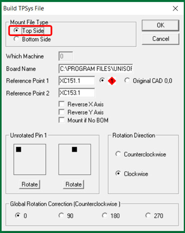
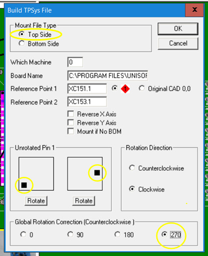
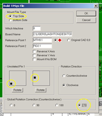
TOP SIDE: For the top side Mydata / Mycronic assembly machine setup file creation in the "Build TPSys File" window set a 270° global rotation and 1 click on the left side UNROTATED PIN 1 box and and 3 clicks on the right side UNROTATED PIN 1 box as illustrated in the picture below.
Note1: For Mydata / Mycronic machines it is recommended that the MARK REFERENCE 1 point for the top side of the PCB assembly ( PCBA ) be located on the bottom left corner of the board when viewed in the Unisoft software. Also it is recommended that the point that is chosen for MARK REFERENCE 1 on the top side is also set to the XY 0,0 origin of the PCB assembly ( PCBA ) using the SET ORIGIN feature.
By doing this the coordinates displayed for the components in the Unisoft software will typically be the same as the coordinates exported to the file to program the assembly machine making verification, if needed, easier. Also the PC board will then usually be located in the first quadrant where the component coordinates (x;y) will both be positive.
Note2: If the UNROTATED PIN 1 box controls do not seem to be changing the rotations in the Mydata output file created than most likely you have a fixed rotation CAD file type that was imported. To resolve this issue please click this link and go to the "1) RESET ROTATION FEATURE" section on that page.
Note3: Some Mydata / Mycronic assembly equipment customers have used the set up as illustrated in the picture below with 1 click on the right side UNROTATED PIN 1 box. However this setting is not the preferred setting for the Top side, the preferred setting is illustrated in the picture above.
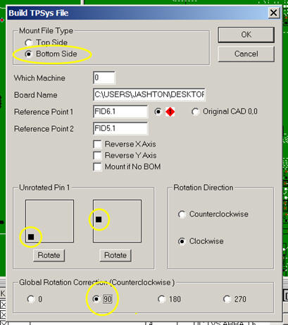
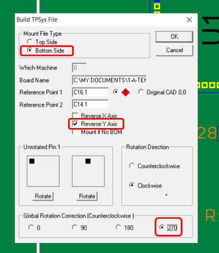
BOTTOM SIDE: For the bottom side Mydata / Mycronic assembly machine setup file creation in the "Build TPSys File" window set a 90° global rotation and 1 click on each of the two UNROTATED PIN 1 boxes as illustrated in the picture below.
Note1: For Mydata / Mycronic machines it is recommended that the MARK REFERENCE 1 point for the bottom side of the PCB assembly ( PCBA ) be located on the bottom right corner of the board when viewed in the Unisoft software. Also it is recommended that the point that is chosen for MARK REFERENCE 1 on the bottom side is also set to the XY 0,0 origin of the PCB assembly ( PCBA ) using the SET ORIGIN feature.
By doing this the coordinates displayed for the components in the Unisoft software will typically be the same as the coordinates exported to the file to program the assembly machine making verification, if needed, easier. Also the PC board will then usually be located in the first quadrant where the component coordinates (x;y) will both be positive.
Note2: In certain cases depending on your Mydata / Mycronic machine model and software version and the type of CAD data imported customers have reported that it was necessary to reverse (mirror) the X Axis when creating the bottom side Mydata / Mycronic programming file to get the correct mount file they needed. If the bottom side data created by the Unisoft software seems to be reversed (mirrored) in your situation then in addition to the settings below also put a checkmark in the box for the field REVERSE X AXIS.
Note3: If the UNROTATED PIN 1 box controls do not seem to be changing the rotations in the Mydata output file created than most likely you have a fixed rotation CAD file type that was imported. To resolve this issue please click this link and go to the "1) RESET ROTATION FEATURE" section on that page.
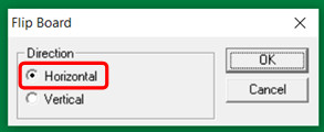
Note4: When viewing the bottom side of the PCB assembly ( PCBA ) in the Unisoft software the board is actually viewed flipped and therefore the X coordinates are more positive as they go from right to left. This is the opposite of viewing the top side of the PCB assembly ( PCBA ) in the Unisoft software where X coordinates are more positive as they go from left to right.