
5 minutes to program your PCB assembly ( PCBA ) AOI machine
Click here for software download & more information!
Fully functional trial licenses,
available at no charge, are normally provided for approximately one month to
allow you to try out the software. Let us know if you're interested.
"Work is the refuge of people who have nothing better to do." - Mark Twain.
Are you tired of dedicating countless hours to programming your PCB inspection
AOI machines? Our Unisoft ProntoAOI software, developed over 40 years, can provide you with more time to pursue your passions and interests.
Think about all the additional time you could spend reading, gaming, or even
relaxing. Just kidding about these, boss.
Seriously, the ProntoAOI
software is used by electronics manufacturers and creates programs for PCB assembly ( PCBA ) Automatic Optical Inspection (AOI) machines & includes the basic features of ProntoVIEW-MARKUP.
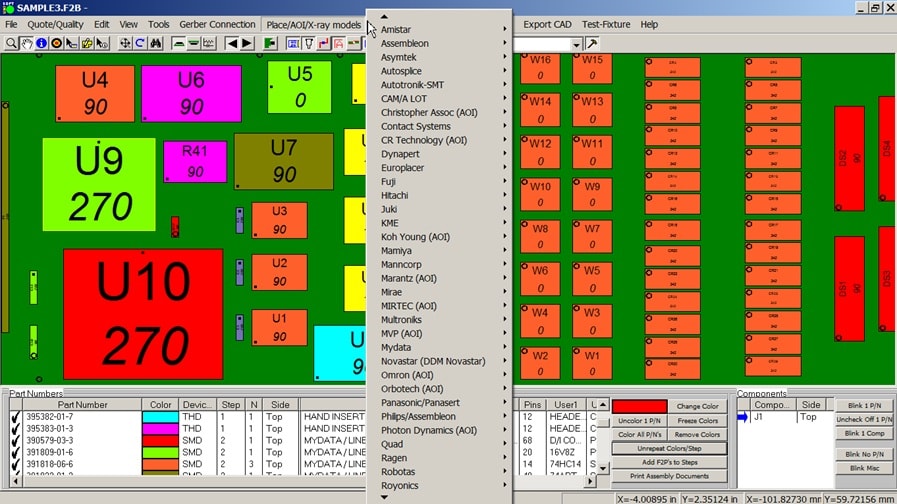
The Unisoft ProntoAOI software translates CAD or Gerber and Bill of Materials
(BOM) files into real reference designators, X/Y body centers, Theta rotation,
part numbers, etc. This data is then used by Process Engineers to program their
AOI machines. ProntoAOI programs popular newer and older AOI equipment. Most
machines are supported such as Agilent, Aleader, AOI Systems, ASC International,
Beijing Torch, Christopher Associates, CR Technology, CyberOptics, DCB
Automation, Goepel Electronics, JT Automation, Jutze Technology, Koh Young,
Landrex Technologies, Machine Vision Products (MVP), Marantz, MEK, Mirtec,
Omron, Orbotech, Parmi, Pemtron, Photon Dynamics, Saki, Samsung, Shanghai Holly,
Test Research, Vi Technology, Viscom, ViTrox, YESTech, YesTek, ZhenHuaXing, etc.
Other AOI machine models can be programmed with standard outputs the Unisoft
software creates. Also some AOI machines need only standard CAD file formats to
program them and the Unisoft software as options available to input one type of
CAD file format and then export a standard CAD file format such as GENCAD,
IPCD356, IPC-2581, MENTOR Neutral, PADS, Fabmaster, .XML, etc. that can then be
used to program those AOI machines. Trial Software:Try
our trial software at no cost. Start using the fully licensed version for as
little as $600. For over 40 years, Unisoft has delivered exceptional value.
ProntoAOI also includes, at no additional charge, the basic features of ProntoVIEW-MARKUP and is used by PCB assembly ( PCBA ) electronic manufacturers with features such as detailed viewing of PC board assemblies and the creation of documents, etc. required throughout the PCB assembly ( PCBA ) process. The software increases efficiency, communications and reduces errors across the production floor. With over 100 features ProntoVIEW-MARKUP aids every department every day on the shop floor of PCB assembly ( PCBA ) manufacturers where it is used by management, assembly, inspection, design, Test, troubleshooting technicians and other personnel. The software creates assembly instructions with unique colors for each part number and step in the assembly process and generates matching kitting labels. Locate any component, pin or part number, finds shorts between traces, netlist, paperless hyperlinked schematic linked to the asssembly, add annotation notes and graphics. The software provides fast PC Board first article inspection and general inspection. Create reports containing device and package type counts with quotation and cost estimations, etc.. With a current license distribute the Unisoft PC Board viewer software to your production floor, vendors, customers, etc. to aid assembly, 1st article inspection, general inspection, repair/rework, technician debug, for better communications, etc. If needed ProntoVIEW-MARKUP can be controlled remotely from your application or equipment via the supplied external API programming interface.
Sample AOI machine setup file created by Unisoft ProntoAOI (all popular machine formats supported):
YESTECH AOI:

.YESTECH_CAD
[Header]
Version= 1
RecipeName= 7807_TOP
Scale= 25.4
InvertXPos= 0
InvertYPos= 0
RotationDir= 1
RotationOffset=0
BoardWidth= 9187.0
BoardHeight= 6364.0
PNLib=
IsSharedPNLib= 0
PkgLib=
PkgNameMap=
IsTopSide= 1
[PartList]
RefID NAME X Y Rot Pkg Description
C144 315-507000-107 5150.00 3048.00 90 S6032T_TOP CAP: TANT 100uF 6.3V 20% CASE 6032
C77 315-406000-047 5871.50 2109.00 0 S3528T_TOP CAP: TANTALUM CHIP 4.7uF 20% 16V EIA 3528
C1121 315-304006-104 1779.00 700.00 90 S0402T_TOP CAP .1uF 16V Y5V 0402
C1055 315-406000-047 5127.00 693.50 90 S3528T_TOP CAP: TANTALUM CHIP 4.7uF 20% 16V EIA 3528
R311 347-000064-536 5694.00 1293.00 270 S0603T_TOP RESISTOR: 53.6 OHM 1% 0603
R165 347-000080-332 3166.00 2688.00 270 S0402T_TOP RESISTOR: 33.2 OHM 1% 0402


MIRTEC AOI:

[Fiducial]
Fid1_X= 0
Fid1_Y= 0
Fid2_X= 0
Fid2_Y= 0
[Part Info]
Coordinate Transform=NO
Part Count=82
#00000001,-53340,11430,342,385848-05-6,CR24,2-PIN THUR-HOLE / UNIVERSAL VCD AUTO INSERT
#00000002,-37465,34925,342,385848-05-6,CR13,2-PIN THUR-HOLE / UNIVERSAL VCD AUTO INSERT
#00000003,6985,57785,161,385848-05-6,CR1,2-PIN THUR-HOLE / UNIVERSAL VCD AUTO INSERT
#00000004,-121920,17145,270,391777-06-8,C2,1206 / CHIP SHOOTER AUTO INSERT


C211     003-W2122104K     5315 4360     0       0402     CAP .1UF 10V CERAMIC 0402
C194     003-W212A104K     567    5 3955     0       0402     CAP .1UF 10V CERAMIC 0402
C125     600-RW1120JW      6145 1575     180   0603     CAP RF 12 PF 600 SERIES
C116     007-1213H473K      5625 1410     90     0603     CAP .047UF 50V CERAMIC 0603
C117     003-0012A104K      8300 1215     0       0402     CAP .1UF 10V CERAMIC 0402
C148     120-77131H121J     5625 2660     90     0603     CAP CERAMIC 120PF 50V 0603 SMD


Part Count=82
#00000001=-869950,539750,180,395422-01-9,U11,SOIC8,I/O CONTROLLER
#00000002=-1155700,273050,90,391818-06-6,U3,SOIC48,74HC14
#00000003=-869950,406400,180,395422-01-9,U12,SOIC8,ILD251
#00000004=-1447800,520700,90,391829-03-3,U4,SOIC20W,74HCT640


<xml version="1.0">
<unisoft version="1.0" units="mils">
<board name="c:\program files (x86)\unisoft\SAMPLE.CAD" width="6910" height="2575">
</board>
<layers>
<layer name="TOP" top="true" bottom="false" sequence="1"/>
<layer name="4" top="false" bottom="false" sequence="2"/>
<layer name="5" top="false" bottom="false" sequence="3"/>
<layer name="BOTTOM" top="false" bottom="true" sequence="4"/>
</layers>
<nets>
<net name="BUFCLK"/>
<net name="IOMCLK"/>
<net name="IDI-16"/>
</component>
<component name="R36" x="-3800" y="550" devicetype="SMD" partno="391729-02-0" layer="BOTTOM">
<outline>
<line x1="-3831" y1="651" x2="-3769" y2="651"/>
<line x1="-3769" y1="651" x2="-3769" y2="449"/>
<line x1="-3769" y1="449" x2="-3831" y2="449"/>
<line x1="-3831" y1="449" x2="-3831" y2="651"/>
</outline>
<pins>
<pin name="1" x="-2250" y="500" component="CR24" net="N_867" pin1="true"/>
<pin name="2" x="-1950" y="400" component="CR24" net="CGND"/>
<pin name="1" x="-1625" y="1425" component="CR13" net="N_829" pin1="true"/>
<pin name="2" x="-1325" y="1325" component="CR13" net="N_871"/>
<traces>
<trace x1="-4575" y1="2000" x2="-4600" y2="1975" net="-RDLTCH" layer="BOTTOM"/>
<trace x1="-4600" y1="1975" x2="-4600" y2="1950" net="-RDLTCH" layer="BOTTOM"/>
<trace x1="-5475" y1="1025" x2="-5475" y2="1100" net="-IOMRD" layer="BOTTOM"/>
<trace x1="-5725" y1="1575" x2="-5725" y2="1625" net="BUFCLK" layer="BOTTOM"/>
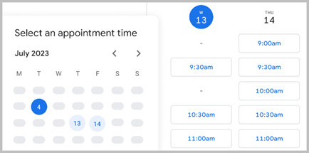
To start or schedule a meeting
Click Here or email us (enable JavaScript for our email addresscad-to-cad.php) or call us (enable JavaScript for our phone number).
In our meeting, we can follow any direction you prefer, for instance:
-- Talk about your requirements, software inquiries, and other concerns.
-- Software demonstrations & training. We have the option to process one of your PC Boards or demonstrate the software using our own data files.
-- Provide you with a fully functional trial version of the software license.
-- etc.
Some features of ProntoAOI:
The ProntoAOI software also includes the basic features of ProntoVIEW-MARKUP:
Other features in the Unisoft software suite:

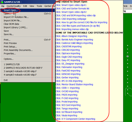
The trial software has HELP for most menu items by hovering over the menu item for a second then click any of the videos, manual or website links to learn about the software.
VIDEO: Click the video above for product overview.
Please double check that your email address is correct.
Email addresses are kept private.
The software download link, more information and periodic updates will be sent to this address.
Optionally to receive your software call us (enable JavaScript for our phone number).

The basic features of ProntoVIEW-MARKUP are included at no additional charge and adds features such as detailed viewing of PC board assemblies and the creation of documents, etc. required throughout the PCB assembly ( PCBA ) process. The software increases efficiency, communications and reduces errors across the production floor. With over 100 features aids every department every day on the shop floor of PCB assembly ( PCBA ) manufacturers where it is used by management, assembly, inspection, design, Test, troubleshooting technicians and other personnel.
The information and figures that follow outline a few of the features of ProntoVIEW-MARKUP or go to the ProntoVIEW-MARKUP page for more detail.
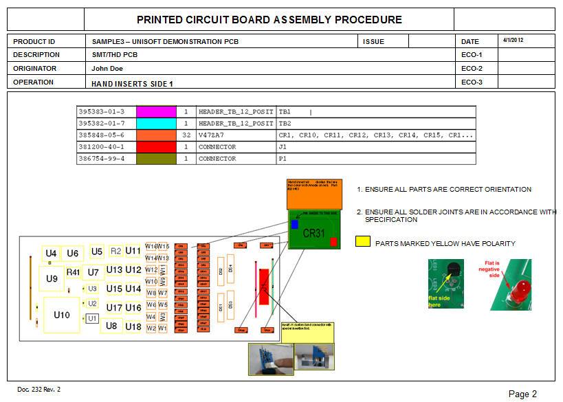
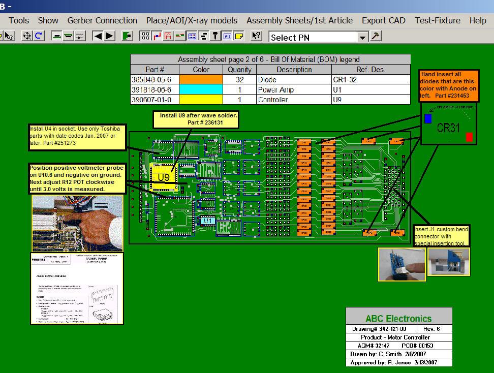
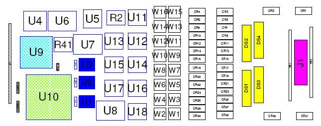
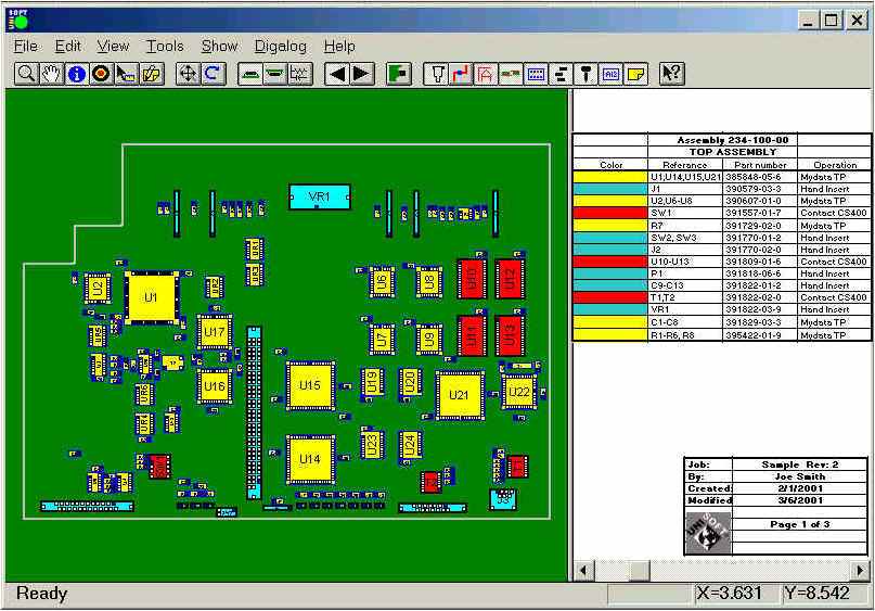
The Unisoft software allows you to quickly create matching assembly lists and assembly drawing sheets for each step in the assembly process. Part numbers are automatically assigned to the assembly step you wish (for example: Step 1 for Hand Inserts, Step 2 Chip Shooter components, etc). The part numbers are then automatically uniquely colored. If needed, overlay annotation notes can be added to each step. Next for each step matching assembly lists and assembly drawings are created. These drawings can either be printed or save to a file (PDF Adobe, etc.) or displayed on the screen.
Download a sample of process and assembly sheet documentation created by this software.


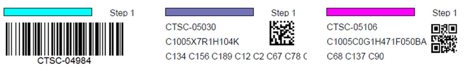
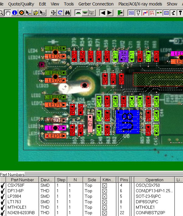
The Unisoft software allows you to quickly create Kitting Labels with barcodes for fast and accurate electronic component kitting. Quickly select the component part numbers for which you wish kitting labels created. Each label contains the part number, unique part number color, step number, p/n description, reference designator, etc. Fast and easy electronic kitting labels for kitting work orders.
Barcodes of various types can be printed on the kitting labels and shown on the display for quick kitting,
fast assembly machine feeder loading, verification, inspection, etc.: 2d-qr code, 2d-data matrix, etc.


This feature of the Unisoft
software allows you to add parts, processes, and other items that are not
part of the actual electrical circuitry on the PC board. These elements can
then be assigned to individual assembly process steps and treated like any
other step within the Unisoft software. You can add just a few additional
steps or, if desired, define the entire PCB assembly process—from the
pre-assembly stage to the main assembly stage, and continuing through the
point at which the fully assembled PCB is integrated into its subassembly.
For more information about this feature,
please click here.
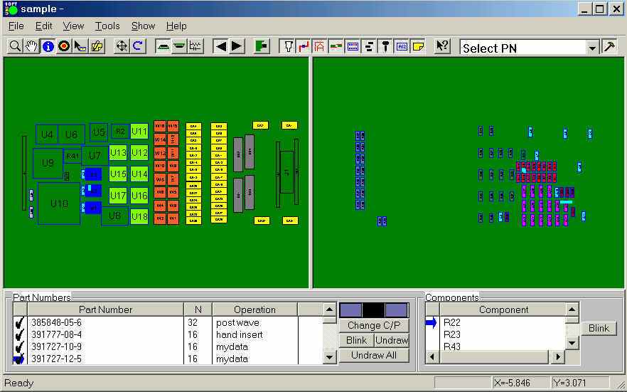
For instance, if you need to add a PC board
card ejector by hand to the assembly process, you can enter that item along
with corresponding annotation text, notes, and pictures. You can then assign
it to a specific assembly step and treat it just like any other process step
in the Unisoft software. In the figures above, we’ve added a non-electrical
part—specifically, a card ejector—labeled "Cardeje1" as its reference
designator, with a part number of CP-390E, onto the PCB and created an
additional step—Step 6—to manually insert that part onto the PCB. Next, we
create and assigned one annotation containing text and another containing a
picture to step 6.
Then, in the example shown in the figure below, we
use the standard Unisoft “Print Assembly Document” feature to print Step
Number 6. If you choose not to print, the operator can simply work from the
on-screen display and complete the assembly—just like with any other step
operation.

Below are some examples of
non-electrical parts and processes that can be involved in completing a PCB
assembly. You may also create as many steps as desired—for example, you can
extend your steps to include pre-assembly and post-assembly processes. For
more details,
please click here.
ASSEMBLY:
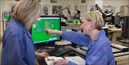
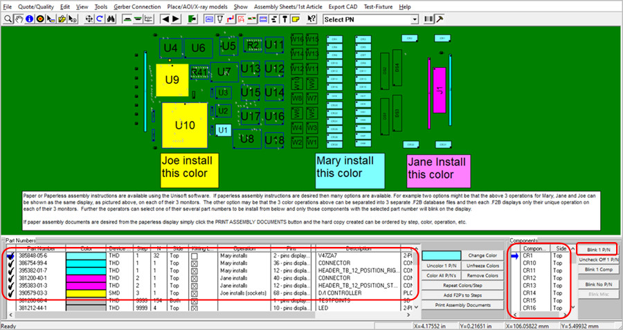
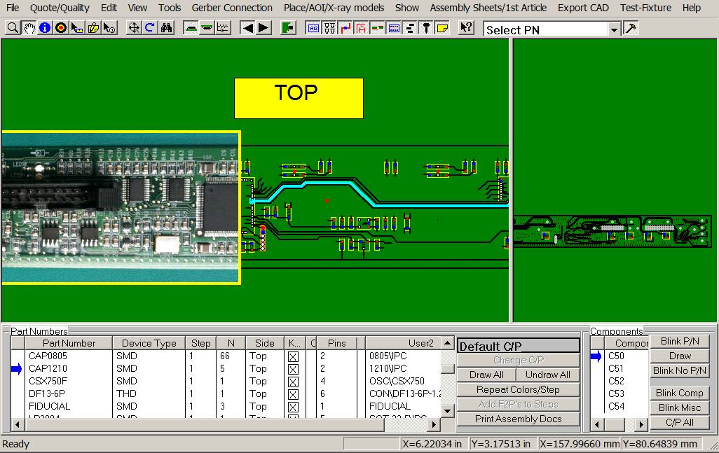
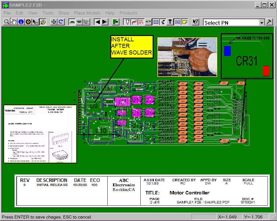
Paper or Paperless assembly instructions are available using the Unisoft software. If paperless assembly instructions are desired then many options are available. For example two options might be that the below 3 operations for Mary, Jane and Joe can be shown as the same display, as pictured above, on each of their 3 monitors. The other option may be that the 3 color operations above can be separated into 3 separate .F2B database files and then each .F2B displays only their unique operation on each of their 3 monitors.
Further the operators can select one of their several part numbers to be install from below and only those components with the selected part number will blink on the display.
If paper assembly documents are desired from the paperless display simply click the PRINT ASSEMBLY DOCUMENTS button and the hard copy created can be ordered by step, color, operation, etc.
Import your PC Board into the Unisoft manufacturing software and you instantly receive a report containing component counts for top and bottom of the PC Board broken down by SMT, Fine pitch, BGA's, Thru-hole, etc. with the cost for each group. You can create as many PCB assembly ( PCBA ) Cost templates as you wish, for example one each for either a Low, Medium or High volume build. This is a great quoting time saver for Contract and OEM manufacturers.


Example of a few lines of a report follows:
PC Board:   123-456
Date:       1-22-2013

    Base 1st Unit Assembly Build Rate (Includes P/N Setup Rate) = 219.18

    Each Unit Assembly Build Rate (Excludes P/N Setup Rate)     = 74.18

    Total Part Number Setup Rate                                = 145.00
________

SMT 2 pins greater than 0402 package type:  Greater than .040 inch distance between pin 1 and 2.
    Top      -  4 = total device count, 8 = total pin count
    Bottom   -  78 = total device count, 156 = total pin count
    Part #'s -  8 = total part numbers
    Base Rate:  49.84 = (0.12 * device count) + (5.00 * part #'s)

SMT 8 pins and greater and 30 mils or less pin spacing (fine pitch):
    Top      -  3 = total device count, 144 = total pin count
    Bottom   -  0 = total device count, 0 = total pin count
    Part #'s -  3 = total part numbers
    BGA's    -  0 = included in above count.
    Base Rate:  15.48 = (0.16 * device count) + (5.00 * part #'s) + (0.75 * BGA count)
Instantly create a component part cost report. This report is used by Contract and OEM manufacturers to quickly estimate component parts costs. The report contains the total component part cost for the PC Board and breakdown by part number.
Report type: Parts count with quotation and cost estimation.

PC Board: Controller
Date: 1-12-09
Total parts cost = $43.31
____
| 381200-40-1 | 1 | $0.23 | $0.23 |
| 381212-44-1 | 4 | $0.07 | $0.28 |
| 385848-05-6 | 32 | $0.45 | $14.40 |
| 386754-99-4 | 1 | $0.16 | $0.16 |
| 389148-06-7 | 1 | $0.06 | $0.06 |
| 390579-03-3 | 1 | $0.80 | $0.80 |
| 390607-01-0 | 1 | $0.65 | $0.65 |
| 391727-10-9 | 16 | $0.04 | $0.56 |
| 391727-12-5 | 16 | $0.04 | $0.64 |
Instantly create a report of the total solder joint count for Defect Per Million Operations (DPMO). This report is used by Contract and OEM manufacturers for quality tracking. The report contains the total solder joints for the PC Board broken down by SMT and Thru Hole and part number.
Report type: Solder joint count with quotation and DPMO estimation.

PC Board: Controller
Date: 1-12-09

Total Solder Joints = 1104
Total SMT Solder Joints = 598
Total Thru Hole Solder Joints = 506
____

SMT 2 pins greater than 0402 package type: Greater than .040 inch distance between pin 1 and 2.
    Top - 4 = total device count, 8 = total pin count
    Bottom - 78 = total device count, 156 = total pin count
    Part #'s - 8 = total part numbers

SMT 8 pins and greater and greater than 30 mils pin spacing:
    Top - 17 = total device count, 290 = total pin count
    Bottom - 0 = total device count, 0 = total pin count
    Part #'s - 8 = total part numbers
    BGA's - 0 = included in above count.

Thru-hole 2 pins:
    Top - 34 = total device count, 68 = total pin count
    Bottom - 0 = total device count, 0 = total pin count
    Part #'s - 3 = total part numbers

Thru-hole 8 pins and greater:
    Top - 24 = total device count, 284 = total pin count
    Bottom - 0 = total device count, 0 = total pin count
    Part #'s - 6 = total part numbers
The Electronic Components Search feature helps you find information such as cost, availability, part shape, electrical specifications, etc. Provides fast searching for electronic parts using your favorite parts search engine for example Octopart, FindChips, Alldatasheets, ECIA Authorized, etc.
Search for electronic parts using the Manufacturer or Vendor P/N for example ERJ-3EKF1002V. Also search by the electronic component number or name such as MAX232, LM393, resistor 10k, shift registers, inverter schmitt trigger, etc.


All types of Bill of Material (BOM) formats can be imported into the Unisoft software and then exported to normalized standard BOM formats that can then be utilized by your other manufacturing software systems such as Part Sourcing, MRP, ERP, etc.


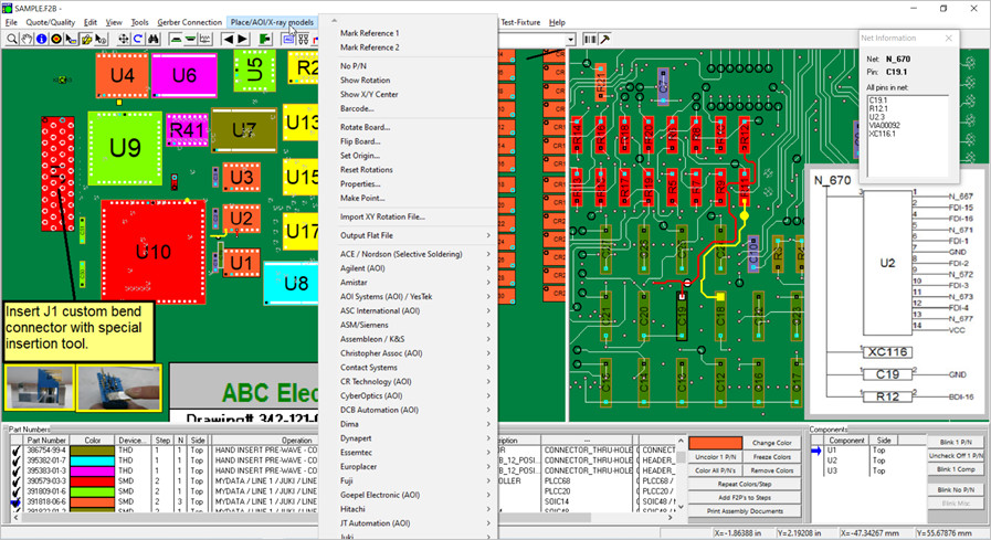
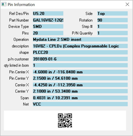
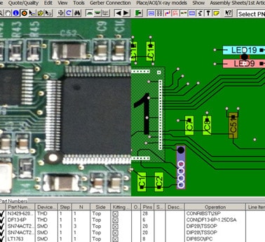
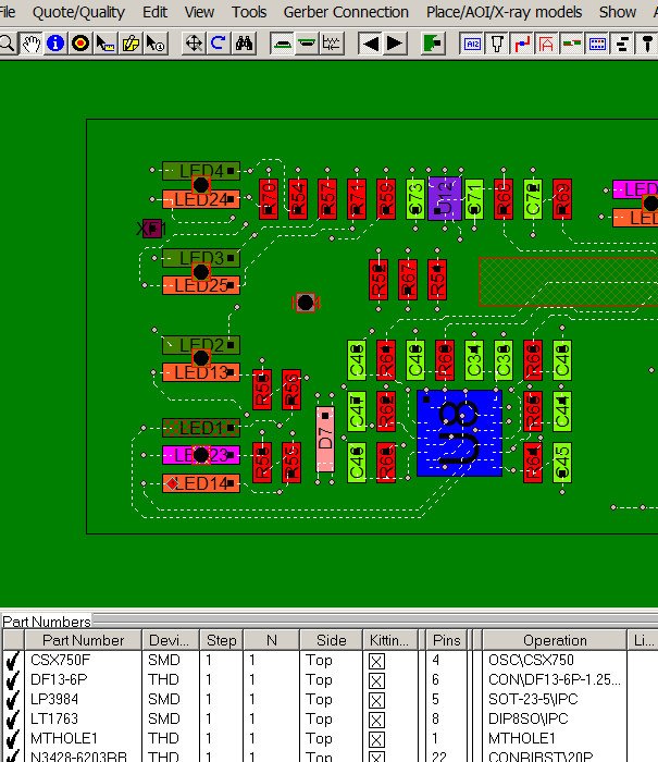
Easier drill down to component pins, trace runs and schematic. Display NETLISTS quickly using the "NET INFORMATION" window that displays the NET NAME of the selected component and pin and all the other pins on the net. The trace run of the selected net is highlighted and all pins on the net blink. If the schematic view is displayed then the net chosen is shown. The user can then select any one of the other pins on the net in the NET INFORMATION box. The result is the NET INFORMATION window will update to the new selected pin and the selected trace highlighted will update also. If the schematic view is displayed then that view will refresh too.


Find shorts between traces, netlists, netnames, component information, etc.
The Unisoft software outputs a single board file of the PCB assembly ( PCBA ) that is compatible with the PCB assembly ( PCBA ) viewer. Customers with a current license can distribute the PCB assembly ( PCBA ) viewer and the Unisoft PCB assembly ( PCBA ) board file to your production floor, other divisions, vendors, customers, etc. to aid assembly, first article inspection, general inspection, repair/rework, technician debug, for enhanced communications, etc.

Unisoft: Manufacturing software since 1985