Further below are the levels of component rotation modification provided via the Unisoft software.
Note the Unisoft software uses the IPC-7351B Level A as its zero degree component orientation rotation default.
There are levels of component rotation modification that are sometimes needed an Unisoft can help with this. Most customers both contract and OEM generally don't seem to have problems with component rotations and then again in certain cases it can be a difficult moving target and maybe more so in legacy designs. The rotation data for the component is used in the automatic assembly and inspection of components on PC boards and therefore it is important that it's consistently correct.
Some speculative thought on why there are sometimes inconsistencies in 0° orientation rotations standards for component packages in some CAD files:
As time moves on there is a positive trend where 0° orientation rotations for component packages are being standardized within the industry. The Unisoft software uses the IPC-7351B Level A as its zero degree component orientation rotation standard.
CAD FILES "WITHOUT" EXPLICITLY DEFINED COMPONENT ROTATIONS: Some CAD files such as IPC-D-356, Unisoft FBA, etc. have component pin data but no data on component rotations. When this is the case then Unisoft automatically calculates the rotation using standard zero degree package orientations (IPC-7351B Level A).
CAD FILES "WITH" EXPLICITLY DEFINED COMPONENT ROTATIONS: When a CAD file is imported into the Unisoft software were the component rotations are explicitly defined in the CAD file then Unisoft uses these rotations and does not calculate the rotation.
To see whether a CAD file type has explicitly defined component rotations or not go to the following webpage
https://www.unisoft-cim.com/importers.php#CAD_&_GERBER_FILE_LISTINGS
and go to the Note listed for the rotation type.

There under ROTATION TYPE if it says "1a" then it is a CAD file without explicitly defined component rotations. If it says "1b" then it is a CAD file with explicitly defined component rotations.
In certain cases you may need to modify the rotation of components. Below are some of the rotation modification features of the UniSoft software that can be used.
When a CAD file is imported into the Unisoft software were the component rotations are explicitly defined in the CAD file then Unisoft assigns these
explicitly defined rotations to the components.
For example in the following CAD file this line indicates the that U14 is
rotated 90 degrees and so on initial import of the CAD file the Unisoft software
assigns a rotation of 90 degrees to U14.
U14 3130-3026 43815000 38100000
90.0 G N 1143000 4191000 0.0 0 -1 0
A large percentage of
CAD
system file formats have explicitly defined rotations.
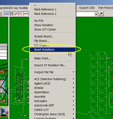
If it is found to be necessary to change the rotation of certain component package shapes in CAD files that have
explicitly defined rotations then the Reset
Rotation feature (see figure below) may need to be used. When the Reset Rotation feature is used the Unisoft software calculates the rotation of the components with the same algorithm and thus the same results as it calculates when CAD files
without
explicitly defined rotations are imported. So
using the Reset Rotation feature sets the component rotation to IPC-7351B Level A standards.
The Reset Rotation feature does not alter the current pin positions of
any components on the display. It only modifies the rotation indicated for the
component, if necessary. For example, if IC component U1 has pin 1 in the upper
left corner before resetting the rotation, it will still be in the upper left
corner afterwards.
Cases where the Reset Rotation
feature may be needed to be used is it is suspected a CAD file imported that has
explicit rotations has incorrect rotations. One example of this scenario might
be for legacy PCB's that where designed earlier in time than when the 0°
rotation standards such as IPC-7351b level A was in place and so the Reset
Rotation feature will correct those rotations back to IPC-7351B level A.
Another example would be for PCB’s with component models incorrectly created,
for example a contract manufacturer receives the CAD file from a OEM
manufacturer where the PCB design CAD person for whatever reason hasn't modeled
the components according to IPC-7351B level A zero degrees rotation standards so
the rotations are incorrect and they need correct rotations to assemble the PCB using their pick and place machine
so the Reset Rotation feature will correct those rotations back to IPC-7351b
level A.
The
difference between CAD files with explicitly defined component rotations and
without: When the CAD file has explicitly defined component
rotations that means in the CAD file there is a field that specifically defines
what the rotation of each component is such as 0, 90, 180 or 270. When a CAD file is imported into
the Unisoft software were the component rotations are explicitly defined then
Unisoft assigns these rotations to the components.
When a CAD file does
not have explicitly defined component rotations then the Unisoft software uses
the available component pin information and automatically calculates component
rotations using the standard zero degree package orientations defined in the
IPC7351B Level A standard.
To Use: Click RESET ROTATIONS from the PLACE/AOI/X-RAY MODELS menu and follow the instructions.
NOTE1: This RESET ROTATION feature replaces the older method that was used to
change the rotation of certain component package shapes in CAD files that have
explicitly defined rotations. The older method was to first export a Unisoft
.FBA file then reimport the that .FBA file and in doing so the rotations were
reset. This newer RESET ROTATION feature results in the same rotation achieved in the older method however this newer method also preserves all current
PC board data such as traces, annotation overlays, etc. which were lost in the
older method.
You can modify the rotation of a part number that is being exported to an assembly or AOI machine.
The MODIFY ROTATION BY PART NUMBER window allows you to modify the rotation of a part number created in the machine output file. For example you may need to flip 2 pin polarized components such as diodes and LEDs 180 degrees. The rotation change is in the output file only and does not affect the displayed PCB. You can save the rotation modification information in the library so that when that part number is seen again on another design the Operation note displayed will indicate a rotation modification is needed and then it can be implemented quickly, for example: "391-521-02-0 Flip 180 diode reversed - Mydata / Mycronic insert". A note such as this in the Operation Field will serve as a reminder to modify the rotation for that part number.
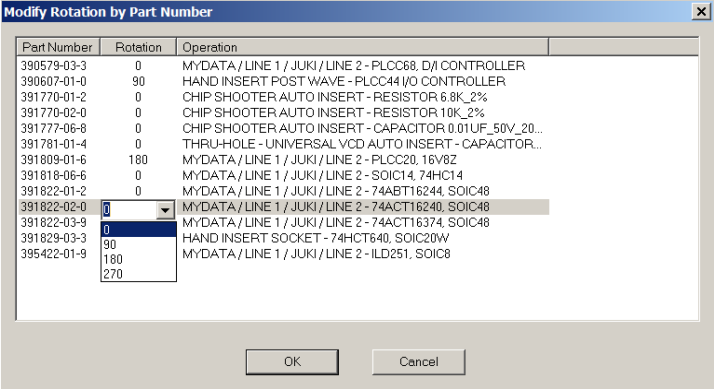
TO USE THE "MODIFY ROTATION BY PART NUMBER" FEATURE: This window will automatically be displayed when generating machine output files. Click the 0 under the Rotation field for the part number you wish to change and add the rotation you wish.
Note: The rotation is added to the existing rotation so for example adding 90 degrees to a part number where a component with that part number is at 180 degrees on the display results in that component being listed as 270 degrees in the output file only and does not effect the rotation of the component on the display.
When creating machine output files such as those used to program assembly machines and AOI machines normally the following build mount file window is displayed. Additional rotation modification options are available in this window.
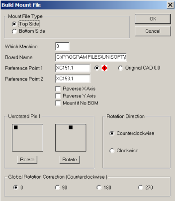
For more information on this Build Mount Window go to the quickstart manual addendum located at https://www.unisoft-cim.com/manual-pronto-detail_mount-file-window.htm. Please refer to Unrotated Pin1, Rotation Direction and Global Rotation Correction on that webpage for additional rotation modification options.
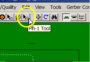
If you wish to rotate individual components then use the "Pin-1 Tool" to change where you wish pin 1 on the component to be and this will change the rotation for those components.
Link to an older IPC document that reflects IPC-7351 recommendation standards for zero degree orientation of packages in the CAD library "Electronic Component Zero Orientation For CAD Library Construction":
Note the Unisoft software uses the IPC-7351B Level A as its zero degree component orientation rotation default.
In the IPC-7351 document most package IC shapes are indicated pin 1 as upper left for 0° rotation and left pin 1 on 2 pin packages.
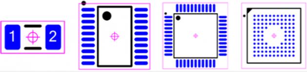
The document also shows assembly machine orientation of the components on the tape feed, etc.
Normally the Unisoft controls to modify component rotation for the top or bottom side are not needed if the PCB assembly ( PCBA ) was laid out per the IPC-7351 specification.
-------------------
Basically what can be interpreted from IPC-7351 is as follows:
The CAD designer should adhere to the recommended rotation standards in IPC-7351 when creating and using CAD models. The component supplier should indicate any rotation modifications for the IPC-7351 standards per the packaging the parts are delivered in such as reels, trays, etc. The pick and place assembly machine should compensate for any variation in rotation from the IPC-7351 standards due to parts packaging.
-------------------
A components land pattern may be used for the same component part from different suppliers and each component supplier may have different orientations on their reels or the components may come in trays. Since the CAD library used by the PCB assembly ( PCBA ) Designers contains a single land pattern, the zero component rotation is defined according to the CAD library and not according to the method the component is delivered to the assembly machine. Then the component suppliers can identify the orientation of the parts on the reels by associating the placement of the part on the reel to zero orientations defined in IPC-7351. So for example if IPC-7351 gives the zero rotation as pin 1 in the upper left then if pin 1 is at the lower left as defined by the component supplier for the tape and reel for the pick and place machine, then the component on the reel each is rotated 90° counterclockwise to correct to the IPC-7351 standard for the CAD library model used for that package.
It's normally not spelled out but this type of standardizing should be the responsibility of the component suppliers and should hold true for the various packaging methods such as tubes, trays or tape and reels the component supplier delivers.
So if rotation standards are followed through from the CAD designer, to the component supplier, to the assembly machine manufacturer then at each step the rotation is known and any corrections necessary are applied. If the CAD designer is adhering to IPC-7351 standards then the component supplier and the assembly machine manufacturer should, as professionals, adjust rotations accordingly if they're modifying the rotation based on the IPC-7351 standard. If Unisoft imports the CAD data files that are to IPC-7351 standards than those rotations should be just past forward and should be correct when the component is inserted by the assembly equipment.
If there are issues because standards haven't been adhered to then Unisoft at different stages provides features within the software to correct rotations.
-------------------
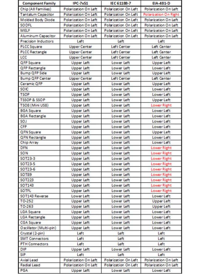
There are normally what is considered 3 world standards IPC-7351 and IEC 61188-7 and EIA-481-D and in the figure below are the component families and their respective Zero Component Orientation for each standard (from Mentor Graphics). Please take note that the standards may vary at the time of your viewing.
IPC-7351B has 2 levels A and B and the majority of standard library component footprints use Level A zero orientation component rotation. The Unisoft software also treats IPC-7351B Level A as its default standard.
Note: The EIA-481-D rotations marked in Red conflict with both IPC and IEC (from Mentor Graphics).
IPC-7351B Level A, which is the standard the Unisoft software uses, is similar to the IPC-7x51 listing in the figure below.
IPC-7351B Level B has different rotations then the IPC-7x51 as listed below but is not often used.
Rotations - Component zero orientation info IPC-7351
Rotations - Understanding component rotations on CAD systems