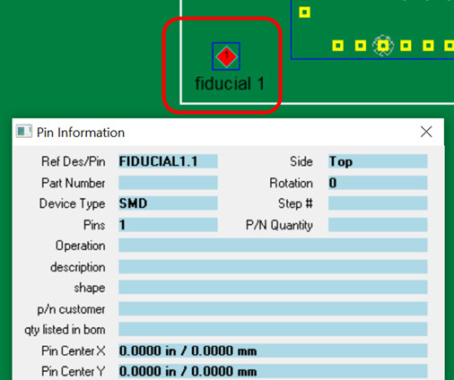
In printed circuit board manufacturing fiducial marks "fiducial points" allow SMT placement equipment "pick & place" to accurately locate and place parts on the PCB . Also AOI inspection equipment, etc.may need these "fiducial points" for lineup as part of the pcb manufacturing process.
Most "pick & place" machines are fed boards for assembly by a conveyor. During the clamped down of the PCB assembly on the conveyor small variances introduced of maybe tenths of a millimeter are enough to ruin the placement of precision components without further calibration and these "fiducial points" add this further calibration. In addition to conveyors other factors can create variances on pick & place machines.
As mentioned, in addition to pick-and-place assembly, fiducial points are sometimes needed for other operations in printed circuit board manufacturing such as AOI optical inspection, PCB assembly Test, selective soldering programming, etc.
There are a number of options available with the Unisoft software for choosing and making these fiducial points. These points in the Unisoft software are referred to as Mark Reference 1, 2, etc.
Companies and engineers have different preferences for the fiducial points they like to use. Also it depends on the type of data that they may receive for the project which may have limited or no fiducial point data readily available to run the job, this can be especially true for Electronic contract manufacturers who experience a large variance in the type of data they get from their customers. Some examples of these lineup points are the actual fiducial marks placed on the PCB or a pin on a component or the edge corners of the PCB or a point off the PCB or plated mounting screw holes, etc. These fiducial points can be either on the pcb board or the pcb panel.
The Unisoft software is quite flexible in choosing and creating these lineup points. In some cases it's as simple as just choosing the fiducials that are readily available from the data files that are displayed in the Unisoft software and in other cases a bit of creativity is sometimes needed.
Important: Set Reference 1 to the XY origin
0,0: For consistent results when exporting your output files to set
up your production equipment from the Unisoft software, it is recommended that
the Reference 1 point set using the Unisoft software also be the XY origin 0,0
for the PCB. So for example, if you set the Reference 1 point on the top side
of the PCB to be a fiducial point in the lower left corner of the PCB and that
point is not currently the 0,0 XY origin for the PCB, then you can click on the
PLACE/AOI... menu at the top of the Unisoft software, then click SET ORIGIN,
then click on the fiducial point where you put the Reference 1 point, and now
that point will be the 0,0 for the PCB. If you are also generating output
file(s) from the Unisoft software for the bottom of the PCB and the Reference 1
point you are choosing for the bottom is not currently the XY origin 0,0 for the
PCB, then repeat the previous process to set it to the XY origin 0,0.
Below are a few options for lineup points and we have assumed you are an experience Unisoft software user. Obviously use the easiest and most sensible method listed below as your first choice as your Mark Reference 1, 2, etc. Please contact Unisoft for help.
Use the standard fiducial marks on the PCB assembly displayed in the Unisoft software for your lineup points (Mark Reference 1, 2, etc.). These marks can be circular marks, etc. of either copper or gold-plated and also silkscreen. The Unisoft Make Component feature maybe used if needed to make fiducial points at these target marks. These points can be either on the pcb board or the pcb panel.
If the board is panelized then there's a good possibility that the fiducial lineup points are on the gerber panel layer. This layer can be overlaid on top of the PCB and then those panel line up fiducial points can be used as your reference lineup points for the PCB.
Create a fiducial mark anywhere you wish using the Unisoft Make Point feature and use those as your fiducial points.
For some low-end boards the plated mounting screw holes a used for lineup points although this yields very low accuracy.
If needed and you have Gerber files you can import and overlay those and then use the Unisoft Make Component feature to make your fiducial points from points on the Gerbers. Note if a gerber point displays as Orphan Pin or ?00000 then it is still raw gerber data and the Make Component feature needs to be used in order to use it as a Mark Reference 1, 2, etc. point. Click here for information.
If you have a silkscreen Gerber layer and you want to use the edge corner of the board as the reference then you could import that layer in and then used the Make Point feature at the corner of the board for your fiducial points.
Another possibility is if you have a drawing of the PCB assembly ( PCBA ) with the dimensions from where you want your fiducial points to be then you could use the Make Point feature and enter those offset dimensions to create the fiducial points.
Another method is if you have a physical bare or loaded PCB assembly ( PCBA ) you could make measurements from a known point for example pin 1 on a component to the fiducial mark and then use the Make Point feature and enter those offset dimensions to create the fiducial points.
In extreme cases you could bring in a drawing or photograph of the PCB assembly ( PCBA ) and line it up and use the positions on the drawing or photograph and then use the Make Point feature and create fiducial points where you wish. Accuracy could be a issue when using this method.
Note: When using the Unisoft software for creating the assembly programming file it is recommended that the MARK REFERENCE 1 point for the top side of the PCB assembly ( PCBA ) be located on the bottom left corner of the board when viewed in the Unisoft software. Also it is recommended that the point that is chosen for MARK REFERENCE 1 on the top side is also set to the XY 0,0 origin of the PCB assembly ( PCBA ) using the SET ORIGIN feature and the same for the bottom side of the pcb.
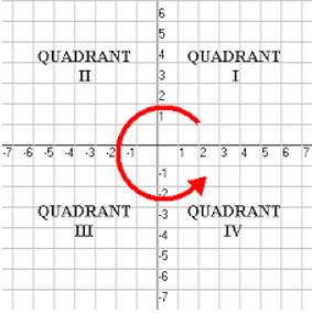
By doing this the coordinates displayed for the components in the Unisoft software will typically be the same as the coordinates exported to the file to program the assembly machine making verification, if needed, easier. Also, the PC board will then usually be located in the first quadrant where the component coordinates (x, y) will both be positive, which is not mandatory but can make working with the PCB more convenient.
We are available any time to go online and review this with you.