Below are three methods for creating multiple assembly machine outputs for one PC Board using the Unisoft software.
Due to the many assembly machine vendors, assembly machine models, feeder types, handlers, component packages, etc. near exact assembly line balancing most engineers feel can only be provided by the actual assembly machine manufacturer. This type of feature is usually very specific custom line optimizing software that the machine vendor such as Fuji, Panasonic, Juki, etc. have created and that software is usually excellent and typically performs its specific task near perfectly. However in some cases the problem with this type of software is usually it is expensive and can be complicated and may support only the newer assembly machine models and does not support a mix of other assembly machine vendors.
Below are three methods the Unisoft software has for creating multiple
assembly machine outputs for one PCB. The recommended ones are either method 1
or 2 and these methods populate the Operation field via the BOM importer in
method 1 and via the Operation library in method 2. In the third method
the BOM is broken up and those part numbers in the BOM are assigned to a
specific assembly machine.
These 3 Unisoft methods allow the
assembly machine operator regardless of assembly machine make or model or mix to
specify which part numbers go on which machines.
To aid in line balancing in the Unisoft software you can use the Operation field import feature of the BOM importer. With this feature you can add a column to the BOM with the operation note you wish for each part number and then import it into the software.
For example in the BOM you could add a column and call it Operation Field and there you can put a notation on how you want to handle the assembly of the part number for example "Insert on machine #2".
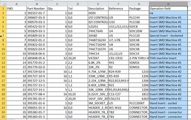
Next using the BOM importing template the Operation field number is specified. For example field # 8 for the BOM above.
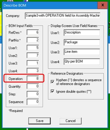
Next the BOM is imported and the Operation field now contains the operation note in the Unisoft Smart Color window.

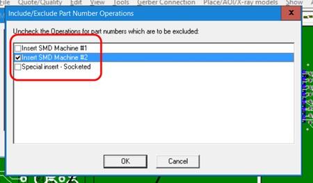
Next when creating the assembly machine file select the machine number you wish from the INCLUDE/EXCLUDE PART NUMBER OPERATIONS window and only those part numbers will be included in the assembly machine output file created. Repeat this step for each machine output needed.
Create and import a Operation library similar to the following regardless of assembly machine make or model or mix to specify which part numbers go on which machines.
395383-01-3    Hand insert - connector
381200-66-4    DNI - Test Points
391809-01-6    Special insert - Socketed
391829-03-3    SMD insert Machine #1 or Machine #3
389148-06-7    Hand insert
391770-02-0    SMD insert Machine #1 only
391770-01-2    SMD insert Machine #1 or Machine #3
390607-01-0    SMD insert Machine #1 only
391822-02-0    SMD insert Machine #1 only
395382-01-7    Hand insert - connector
391822-01-2    SMD insert Machine #1 only
390579-03-3    SMD insert Machine #1 only
391781-01-4    SMD insert Machine #2 or Machine #3
391777-08-4    SMD insert Machine #2 only
385848-05-6    THD machine insert
395422-01-9    SMD insert Machine #1 or Machine #3
391818-06-6    SMD insert Machine #1 or Machine #3
391729-02-0    SMD insert Machine #2 or Machine #3
381200-40-1    Hand insert
386754-99-4    Hand insert
391727-14-1    SMD insert Machine #2 only
381212-44-1    Hand insert
391727-13-3    SMD insert Machine #2 only
396051-01-4    Hand insert - connector
391727-12-5    SMD insert Machine #2 or Machine #3
391822-03-9    SMD insert Machine #1 only
391727-10-9    SMD insert Machine #2 only
Details on how to create an Operation library can be found in the "Assigning operations text to each part number" section of the ProntoVIEW-MARKUP software installation and tutorial page.
After the Operation library has been imported the Operation field will now contain the operation notes in the Unisoft Smart Color window.
Next when creating the assembly machine file select the machine number you wish from the INCLUDE/EXCLUDE PART NUMBER OPERATIONS window and only those part numbers will be included in the assembly machine output file created. Repeat this step for each machine output needed.
An older method that has been used for some time and can still be used is to break up the BOM for the PCB assembly ( PCBA ) into smaller segments each of which represents one of the machines in the line you wish to create an assembly machine program for.
For example if you are going to run a particular PCB assembly ( PCBA ) on two different assembly machine lines you would take the initial BOM and save it into two segments with the part numbers in each segment that would be representative of those part numbers that will be inserted on each assembly machine.
Next the first BOM segment is imported into the Unisoft software and the assembly machine program created and only those components in that BOM segment will be included in the assembly machine program generated. For example components to be placed on Machine #1.
The BOM is then cleared from the Unisoft display by clicking "Clear BOM" and the second BOM segment is imported and the assembly machine program is created from the second BOM segment and only those components in that BOM segment will be included in the assembly machine program generated. For example components to be placed on Machine #2.
Please contact Unisoft with any questions and for training on the features above.