- Software Products
- Trial Software
- CAD Translation
- Testimonials
- Overview
- Pricing
- Knowledge Base
- Contact Us -
- Languages
For help contact Unisoft and we can go online with you.
Important: Much of the populating of database tables when setting up CELLS Workflow is done using the CELLS Route Builder which provides a natural way to populate the NEXT_STEP, DEFECTS, DOCUMENTS, etc. tables by using a spreadsheet.
Using the CELLS Route Builder you can enter data according to the flow of the process being described rather than entering data directly into the NEXT_STEP table in a fragmented, out-of-order manner.
It is recommended that you use the CELLS Route Builder when creating new processes for CELLS Workflow.
The information in this manual below is for reference and provides alternate means of populating the database tables and other information that maybe useful. Again it is recommended to use the CELLS Route Builder when setting up a new process for CELLS Workflow. Link to the CELLS-Route-Builder.
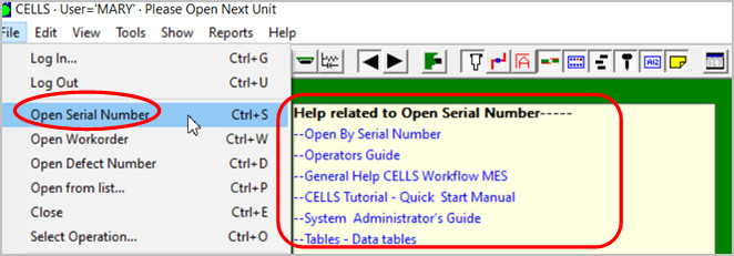
Note: The CELLS Workflow MES has HELP for most menu items by hovering over the menu item for a second then click any of the videos, manual or website links.
Related links:
CELLS is powerful manufacturing software that is easy to use. Some of the features include:
Please see the QUICK-START.DOC in the CELLS directory for the latest details on configuring CELLS and running the sample tutorial provided.
CELLS supports any ODBC compliant database. In this guide we will be using Microsoft Access. A sample CELLS database cells32.mdb is supplied that can be modified.
The following tables must be populated first in order for the CELLS software to work properly. The fields in these tables do not relate to fields in any other tables. It is a good idea to have a flowchart of the routing process you wish to create.
The following tables are populated after the above tables are populated. The above tables will provide you the fields that the following tables make reference to.
There are six operations defined by the system in the Operations table. These operations are defined first. The operations are:
| $START | The first customer defined step in the process. This is the first step defined. |
| $DONE | Where the unit will go when it passes. This is the last step defined. |
| $SCRAP | Where the unit is sent when it cannot be repaired. |
| $ALL | This is not an operation; this will be used later when defects are generated. |
| $SERIALIZE | Used internally when the unit transitions from an un-serialized unit to a serialized unit. |
| $ANYTIME | Advanced — roving inspections. |
Note: The $ (dollar sign) must always appear in front of the system defined fields, otherwise the system will fail to operate.
Other rows in the Operations table are user defined. Figure 1 displays user and system defined fields included in the Operations table. One row is required for each step in the process. These fields can be modified to suit your system requirements and type of business.
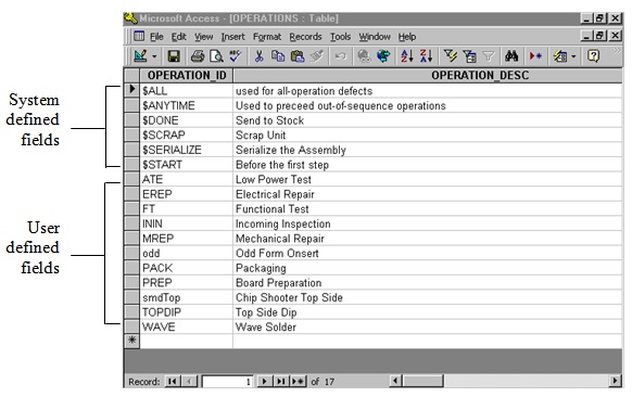
Figure 1. Operations Table
To modify the Operations table in the sample database:
| Field | Description |
|---|---|
| OPERATION_ID | A step in a process. One row is required for each step in a process. |
| OPERATION_DESC | The description of the step. |
| YN_WORK_ORDER_ID | If there is a "Y" in this field, the step will accept a unit by a work order number. If there is a "N", the step will not accept the unit by work order number. |
| YN_SERIAL_NO | If there is a "Y" in this field, the step will accept a unit by a serial number. If there is a "N", the step will not accept the unit by serial number. |
All the fields in the Defects table are user defined. Follow steps 3-6 in the Operations Table instructions to modify the Defects table. See Table 2 for Defects table fields and descriptions.
| Field | Description |
|---|---|
| DEFECT_ID | The defect Id. |
| DEFECT_DESC | The description of the defect. |
| ENABLE_REFDES | If this field is checked, "Unit 1" and "Component 2" areas on the Enter History Item dialog box are activated (see Figure 2). |
| ENABLE_OTHER_ID | If this field is checked, "Other ID" area on the Enter History Item dialog box is activated (see Figure 2). |
| SHOW_ID | If checked, the Defect ID of the record logged will be displayed after the defect is logged (e.g., this number can be attached to a removed subassembly). You can then open the unit by the Defect ID (File, View Defect ID). |
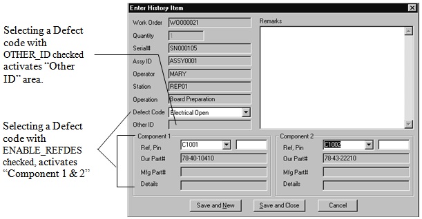
Figure 2. Enter History Item dialog box
The Data Items table collects data and sets up the validation rules for in any process in the plant.
Follow steps 3-6 in the Operations Table instructions to modify the Data Items table. See Table 3 for Data Items table fields and descriptions.
| Field | Description |
|---|---|
| DATUM_ID | The data item Id. |
| DATUM_DESC | The description of the data item. |
| DATUM_TYPE | This is a validation field and does the following checks to DATUM_TYPE: If the field is text, then DATUM_MIN and DATUM_MAX fields are checked. If the field is yymm, the data must be four places with the last two digits between 01-12. All data must be digits. If the field is INT, the data must be all digits. DATUM_MIN and DATUM_MAX fields are also checked. A minus (-) sign is allowed. If the field is DEC, the data must be all digits but can have one dot (.). DATUM_MIN and DATUM_MAX fields are also checked. A minus (-) sign is allowed. Any other fields will cause an error. |
| DATUM_MIN | Minimum character length matching the DATA_TYPE. |
| DATUM_MAX | Maximum character length matching the DATA_TYPE. |
| DATUM_MIN_LEN | Minimum length of data. This field is not checked by the system. |
| DATUM_MAX_LEN | Maximum data to match data type. This field is not checked by the system. |
Note: It is possible to add additional Data Types. See your UNISOFT Representative.
The Data Entry table relates to the Data Items table. This table collects data at a particular operation.
Follow steps 3-6 in the Operations Table instructions to modify the Data Entry table. See Table 4 for Data Entry table fields and descriptions.
| Field | Description |
|---|---|
| ID | The data entry Id. This automatically added to each entry. |
| PROCESS_ID | A valid process Id. This refers to the Processes table. |
| OPERATION_ID | A valid operation Id. This refers to the Operations table. |
| SUB_LOCATION | Used this field if you want to collect two of the same DATUM_IDs at the same step. You then have to enter a unique SUB_LOCATION for that step. |
| YN_REQUIRED | If a "Y" is entered, the user cannot proceed to the next step until data is entered. |
| SORT_ORDER | Effects how the list of data entries appears in reports. |
The Conditions table is used to list the situations that reject or move a unit to the next step. This table includes all possible outcomes from a step in the process. The system $PASS field has to be defined in the Conditions table. All other fields in this table are user defined.
Follow steps 3-6 in the Operations Table instructions to modify the Conditions table. See Table 5 for Conditions table fields and descriptions.
| Field | Description |
|---|---|
| CONDITION_ID | The condition Id. $PASS must be defined in this table. |
| CONDITION_DESC | Description of the condition Id. |
The Users table is used to enter users who will be authorized to use the system. Once a user is added to the table, they cannot be deleted but can be disabled (see ENABLE_FLAG).
Follow steps 3-6 in the Operations Table instructions to modify the Users table. See Table 6 for User table fields and descriptions.
| Field | Description |
|---|---|
| USER_ID | The user Id. |
| USER_NAME | The user's name. |
| PASSWORD | The user's password. |
| ENABLE_FLAG | Entering an "N" in this field prevents an unauthorized user from using the system. |
| USER_GROUP | An assigned group for the user. This is especially helpful in the User Operations table. By grouping users, you do not to enter a user for each operation. |
The Stations table lists the physical locations where the PCs are located (e.g., address of the PC). Once a station is added to the table, it cannot be deleted but can be disabled (see ENABLE_FLAG).
Follow steps 3-6 in the Operations Table instructions to modify the Stations table. See Table 7 for Stations table fields and descriptions.
| Field | Description |
|---|---|
| STATION_ID | The station Id. |
| STATION_DESC | The station description. |
| ENABLE_FLAG | Entering an "N" in this field disables the station. |
The Processes table is where each process is named, described, and the step you go to after $START.
Follow steps 3-6 in the Operations Table instructions to modify the Processes table. See Table 8 for Processes table fields and descriptions.
| Field | Description |
|---|---|
| PROCESS_ID | The process Id. |
| PROCESS_DESC | The process description. |
| STARTING_STEP_ID | The step where you go after $START. |
The Operation Defects table defines a relationship between two tables, the Operations and Defects. Defects are filtered by the current operation. This prevents a user from having to go through the entire list of defect codes to find the exact code needed. The "pairs" have to be defined in this table.
Follow steps 3-6 in the Operations Table instructions to modify the Operation Defects table. See Table 9 for Operation Defects table fields and descriptions.
| Field | Description |
|---|---|
| OPERATION_ID | The operation Id. This relates to the Operations table. |
| DEFECT_ID | The defect Id. This relates to the Defects table. |
| ENABLE_FLAG | Entering an "N" in this field disables the operation/defect and prevents the defect from appearing on the list of defects. |
The Assemblies table describes items that are built in the plant. Included in this table are serial number and work order patterns.
Follow steps 3-6 in the Operations Table instructions to modify the Assemblies table. See Table 10 for Assemblies table fields and descriptions.
| Field | Description |
|---|---|
| ASSY_ID | The assembly Id. |
| BOARD_FILE | Depending on the age of your database, this field may be required. Otherwise the field is obsolete and not used. |
| PROCESS_ID | The default process Id. It does not effect processing. |
| SERIALNO_PATTERN | Matches a serial number pattern. For example: SN_ _ _ _ _ _ will match all serial numbers beginning with "SN" followed by six digits. If the field is left blank, no matching will occur. |
| WORKORDER_PATTERN | Matches a work number pattern. For example: WO_ _ _ _ _ _M will match all work numbers beginning with "WO" followed by six digits and ending with "M". If the field is left blank, no matching will occur. |
The Next Step table defines the sequence of steps in a process. Each row in the table represents a transition between two operations (OPERATION_ID to NEXT_OPERATION_ID). A unit can proceed to the next operation when a condition is met (CONDITION_ID).
Follow steps 3-6 in the Operations Table instructions to modify the Next Step table. See Table 11 for Next Step table fields and descriptions.
| Field | Description |
|---|---|
| PROCESS_ID | The process Id. This relates to the Processes table. |
| OPERATION_ID | The operation Id. This relates to the Operations table. |
| CONDITION_ID | The condition Id. This relates to the Conditions table. |
| YN_DEFAULT | Entering a "Y" in this field allows the user to press ENTER to move to the next step. |
| SORT_ORDER | This affects how the list of next step entries appears in reports. |
| YN_DEFECT_REQ | Entering a "Y" in this field does not allow the user to move to the next step without entering a defect code. |
| NEXT_OPERATION_TYPE |
|
| NEXT_OPERATION_ID | The next operation where the unit is going. |
The Work Order table defines how many units are being built, the range of serial numbers used in the process, and what process is used.
Follow steps 3-6 in the Operations Table instructions to modify the Work Order table. See Table 12 for Work Orders table fields and descriptions.
| Field | Description |
|---|---|
| WORK_ORDER_ID | The work order Id. |
| WORK_ORDER_DATE | The date and time the work order was created. This field does not affect processing but is kept for reporting. |
| WORK_ORDER_QTY | The number of units being built. |
| SERIAL_NO_MIN SERIAL_NO_MAX |
The range of serial numbers that should match the serial number pattern from the assembly table. |
| ASSY_ID | The type of unit being built by the work order. |
| SALES_ORDER_ID | This field does not affect processing but is kept for reporting. |
| PROCESS_ID | This field identifies the process that then identifies the steps. |
| BOM_ID BOM_REV |
These fields do not affect processing but are kept for reporting. |
The Documents table lists documents, CAD files, locations of the documents (file name or html address), and text appearing on the View menu. See Figure 3 for an example of the View menu.
Follow steps 3-6 in the Operations Table instructions to modify the Documents table. See Table 13 for Documents table fields and descriptions.
| Field | Description |
|---|---|
| ASSY_ID | The assembly Id. This relates to the Assemblies table. |
| APPLIES_TO | If the field contains PCB, the document applies to the entire assembly. If the field contains F2B (annotation file), the document applies to the entire assembly but is only available when that specific view is active. If the field contains a REFDES or Part #, the document appears in the context menu when an applicable component on a board is clicked with the Info tool selected. |
| MENU_TEXT | The text you want appear on the View or Context menu. |
| URL | The location of the CAD file, annotation file, or document file. |
| OPERATION_ID | The operation Id. This relates to the Operations table. If this field is not blank, the document in question appears only when the operation is named. |
| MENU_SORT | Documents and files are listed by the sort order value entered here. If blank, the system will list the items as they are entered into the database. |
| YN_DEFAULT | Entering a "Y" in this field will make the document display automatically when the unit is first opened. |
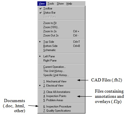
Figure 3. View Menu
The User Operations table is used to assign users to operations. If the user is not listed on the table, the user is qualified for every operation. If a user is listed for an operation, the user is only authorized for the operation listed.
Follow steps 3-6 in the Operations Table instructions to modify the User Operations table. See Table 14 for User Operations table fields and descriptions.
| Field | Description |
|---|---|
| ID | The user operations Id. This automatically added to each entry. |
| USER_ID | The user Id. This relates to the Users table. |
| OPERATION_ID | The operation Id. This relates to the Operations table. |
Note: Using a USER_GROUP in the USER_ID field in this table allows you to assign a group of users to an operation.
The WIP table tracks where assemblies have been and where they are going. This table is a result of output from the system. You have to initialize the WIP table as work orders are created. As work orders are created, a row has to be created in this table for each work order. This row will then transition the number of units from $START to the first operation in the process.
Follow steps 3-6 in the Operations Table instructions to modify the WIP table. See Table 15 for WIP table fields and descriptions.
| Field | Description |
|---|---|
| ID | The record number. This automatically added to each entry. |
| WORK_ORDER_ID | The work order Id. This relates to the Work Orders table. |
| SERIAL_NO | The serial number. |
| OPERATION_ID | The operation Id. This relates to the Work Operations table. |
| CONDITION_ID | The condition Id. This relates to the Work Conditions table. |
| NEXT_OPERATION_TYPE | The next operation type. This relates to the Next Step table. |
| NEXT_OPEATION_ID | The first step in the process. |
| QUANTITY | Number of units moving from OPERATION_ID to the NEXT_OPERATION_ID. |
| DATE_TIME | Date and time the movement was initiated. |
The History table is a result of output from the system. As CELLS processes information, the rows are generated. This table does not require setup from the system administrator.
The Sub Assembly table is a result of output from the system. This table keeps track of which subassemblies have been installed in which assemblies. This table does not require setup from the system administrator.
You can create documents in a word processor (Microsoft Word), web page creator or even a spreadsheet program (Microsoft Excel).
| File saved as: | Will open: |
|---|---|
| .html | Explorer (captive browser) |
| .doc | Word or Word viewer |
| .F2P | Main board display with annotations and overlays |
| .F2B | Main board display |