CAD file comparisons can be done quickly using the Unisoft software. There are two types of comparisons that can be done with the Unisoft software. One type of comparison is using the data of the two files and comparing them for differences and the other is a visual comparison of the PC boards. Below we will discuss the visual comparison method. Click here for the data comparison method.
Using overlaying of the two PC Boards and then comparing visually most changes made between revisions can be identified for example the reference designators, the pins, the XY locations of the pins, via XY, the trace runs, the netlist, gerber silk screen, gerber artwork, etc. The total time to do the setup for the 2 PC Boards to be compared on the Unisoft software is typically 2 to 5 minutes then the visual comparison can begin. Below is a brief outline of the process and it assumes you have some previous working knowledge of the software. We are available anytime to go online and review this software feature with you.
The Unisoft software can also compare Bill of Materials (BOM) files. For more detail on BOM comparison click comparing Bill of Materials (BOM) files.
TO USE: For CAD file visual comparisons import the first CAD file to be compared into the Unisoft software. If you wish at this point you can change the element colors such as pins, traces, etc. and using different colors can help any discrepancies between the two PCB's stand out. This can be done by clicking FILE from the main menu then click OPTIONS and then you will see the SCREEN SETTINGS tab and the colors of elements listed under OBJECT TYPE can be changed there. For example you may wish one of the PCB's to have red trace runs and the second PCB assembly ( PCBA ) to have yellow trace runs this way making it visually easier to detect any differences in trace runs.
Next take a snapshot picture of the top side of the PC Board displayed and you can do that using any one of the many available free and or low-cost screen capture snapshot utilities and save the file. If you need to inspect the bottom of the PCB assembly ( PCBA ) also then take a snapshot picture of the bottom side of the PC Board displayed and save the file.
Next import the second CAD file and this will replace the first CAD file on the display.
Next create an annotation overlay with the ANNOTATION TOOL icon located in the icons at the top of the display under the main menu and import the picture just saved of the first PCB assembly ( PCBA ) screen captured into that annotation. Click on the annotation and click STRETCH GRAPHIC, etc. and resize and reposition the annotation to line up with the second PC Board currently displayed. Next send the annotation to the back of the display by clicking on the annotation and select SEND TO BACK OF PCB assembly ( PCBA ) ELEMENTS DISPLAYED. If inspection of the bottom side of the PCB assembly ( PCBA ) is required then repeat this paragraph using the bottom side PCB assembly ( PCBA ) screen capture file just saved.
Next to view the annotation loaded better shut off the surface mount and thru hole component outlines on the display. This is done by clicking SHOW from the main menu then click COMPONENT OUTLINES and SMD COMPONENTS to turn them off. By doing this it will allow you to see through to the different element details you need to compare on the annotation underneath.
You are now ready to proceed with your visual inspection.
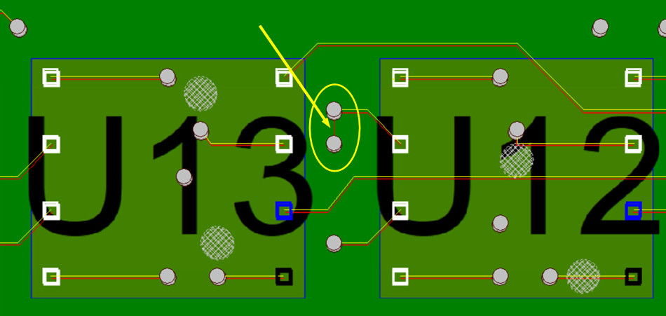
The picture below is an example of what you may see on the display. What was done below was that PCB assembly ( PCBA ) 1 and PCB assembly ( PCBA ) 2 where lined up deliberately just slightly offset so that any discrepancies between the two designs would stand out. Also the trace runs on the first PCB assembly ( PCBA ) where set to red and on the second PCB assembly ( PCBA ) to yellow. Again as mentioned above you can use color as you wish on the different elements of the PCB assembly ( PCBA ) for example pin data, reference designators, traces, component outlines, etc.
At this point discrepancies should stand out, for example in the figure below circled in yellow with the pointer is a red trace run on PCB assembly ( PCBA ) 1, however the matching yellow trace run on PCB assembly ( PCBA ) 2 is missing and so this indicates a discrepancy between the two designs.
We are available any time to go online and review this software feature with you.